Coil configuration having a coil brace of an electromagnetic drive

a technology of electromagnetic drive and coil brace, which is applied in the direction of engine starters, magnetic bodies, machines/engines, etc., can solve the problems of high mechanical wear of pinions and teeth, inability to switch off starters, and greatly limited design possibilities with respect to dynamic response and maximum admissible on-period, so as to achieve simple and cost-effective construction

Active Publication Date: 2011-08-23
SEG AUTOMOTIVE GERMANY GMBH
View PDF13 Cites 11 Cited by
  • Summary
  • Abstract
  • Description
  • Claims
  • Application Information

AI Technical Summary

Benefits of technology

[0008]According to the present invention, the first delimitation of the tube-shaped coil brace of the coil configuration has on its side, facing away from the second delimitation, an axial recess for accommodating the pull-in winding. The delimitations thus executed, which advantageously are developed to be of one piece with the tube-shaped coil brace, enable a simple and cost-effective construction of the coil configuration, in which the pull-in winding and the holding winding are situated in two different chambers on the coil brace. The pull-in winding, in this context, is not wound up or wound on the coil brace, as in the related art. Instead, the pull-in winding is formed in a prior step, and is subsequently pushed into the axial recess of the first delimitation. That is, the pull-in winding is mounted on the coil brace independently of the holding winding, whereby advantages come about in manufacturing and assembly.
[0011]Because of the optimum number of turns of the pull-in winding, there comes about, for the design of the layers of windings, a requirement for two windings and two layers, which, according to one refinement of the present invention, is fulfilled in that the windings, or the wires of the windings are situated not (axially) side-by-side but (radially) one over another, so that the windings of the pull-in winding lie in a common plane. Because of this space-saving arrangement, sufficient space is yielded, at the same time, for the windings of the holding winding.
[0015]According to one refinement of the present invention, the radial recesses and / or the axial recesses are developed in such a way that the pull-in winding and the holding winding are adjacent axially, or axially and radially. Because the holding winding is developed to be axially and radially adjacent to the pull-in winding, it is possible to prepare a large number of holding winding turns, without having to increase the overall length of the coil brace in the process.
[0017]In one additional specific embodiment of the present invention, the pull-in winding is developed in such a way that it acts in the opposite direction to the holding winding. For this reason, the entire magnetic field is weakened during the meshing process, whereby it takes longer, at a constant torsional current. As a result, the torsional angle of the drive pinion during the meshing process is about twice as big, whereby the component stress of pinion and toothed wheel is reduced, since the probability that a tooth tip, of a tooth of the pinion, hits a tooth tip, of a tooth of the toothed wheel, is greatly reduced.

Problems solved by technology

In the case of single-stage starter solenoid switches, which only effect an axial shifting of the pinion, a large proportion of tooth-against-tooth positions occur, which are resolved using the large spring force of a meshing spring and using a high drive torque of the starter, whereby a high mechanical wear is created on the pinion and the toothed wheel.
Otherwise it is not possible to switch off the starter.
Because of a low-resistance design of the pull-in winding for providing the torsional current, and because of the specification of the equality of turns of the pull-in winding and the holding winding, the design possibilities with respect to dynamic response and a maximum admissible on-period are greatly limited.

Method used


Image

  • Coil configuration having a coil brace of an electromagnetic drive
  • Coil configuration having a coil brace of an electromagnetic drive
  • Coil configuration having a coil brace of an electromagnetic drive

Examples


Embodiment Construction

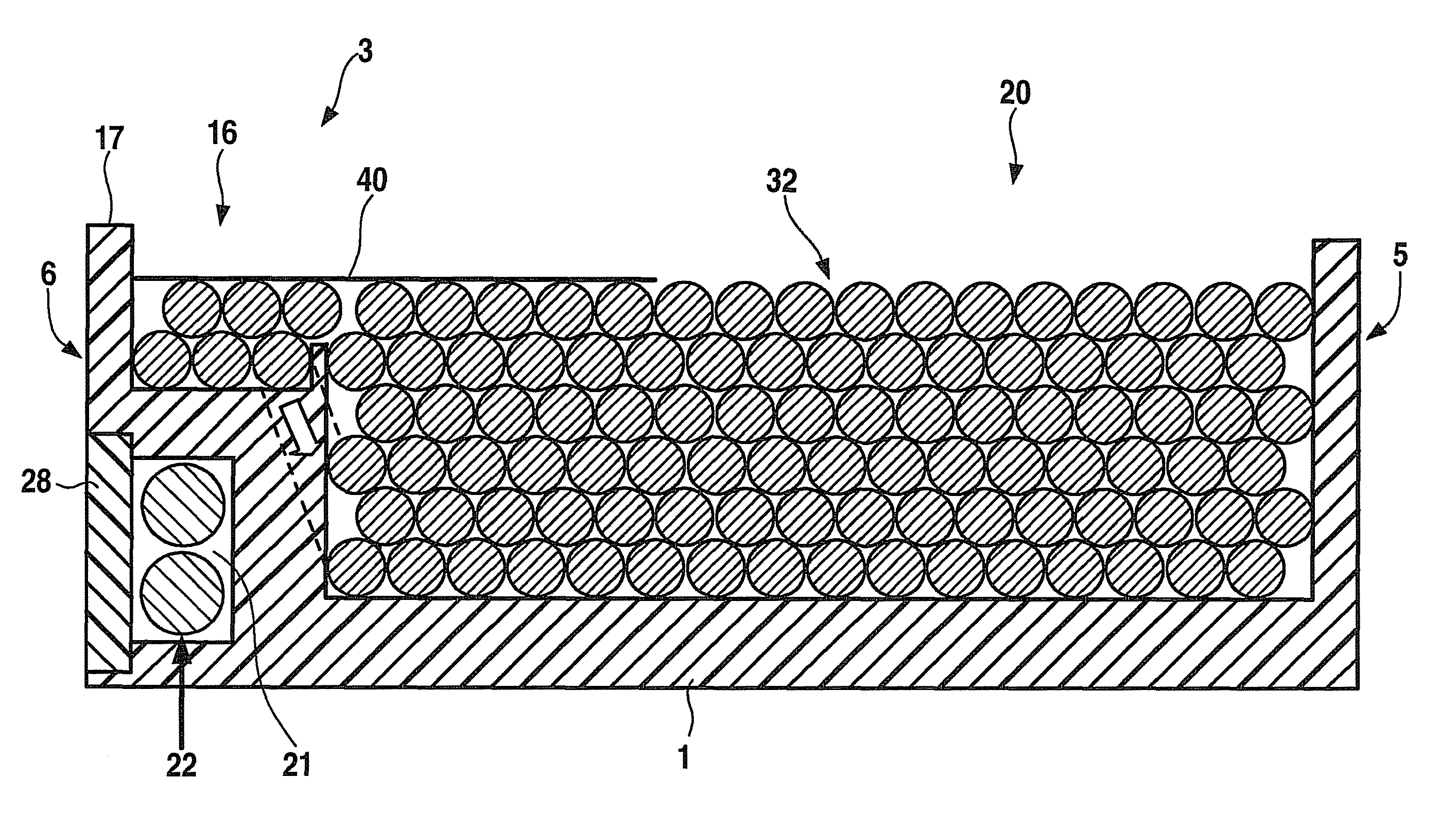
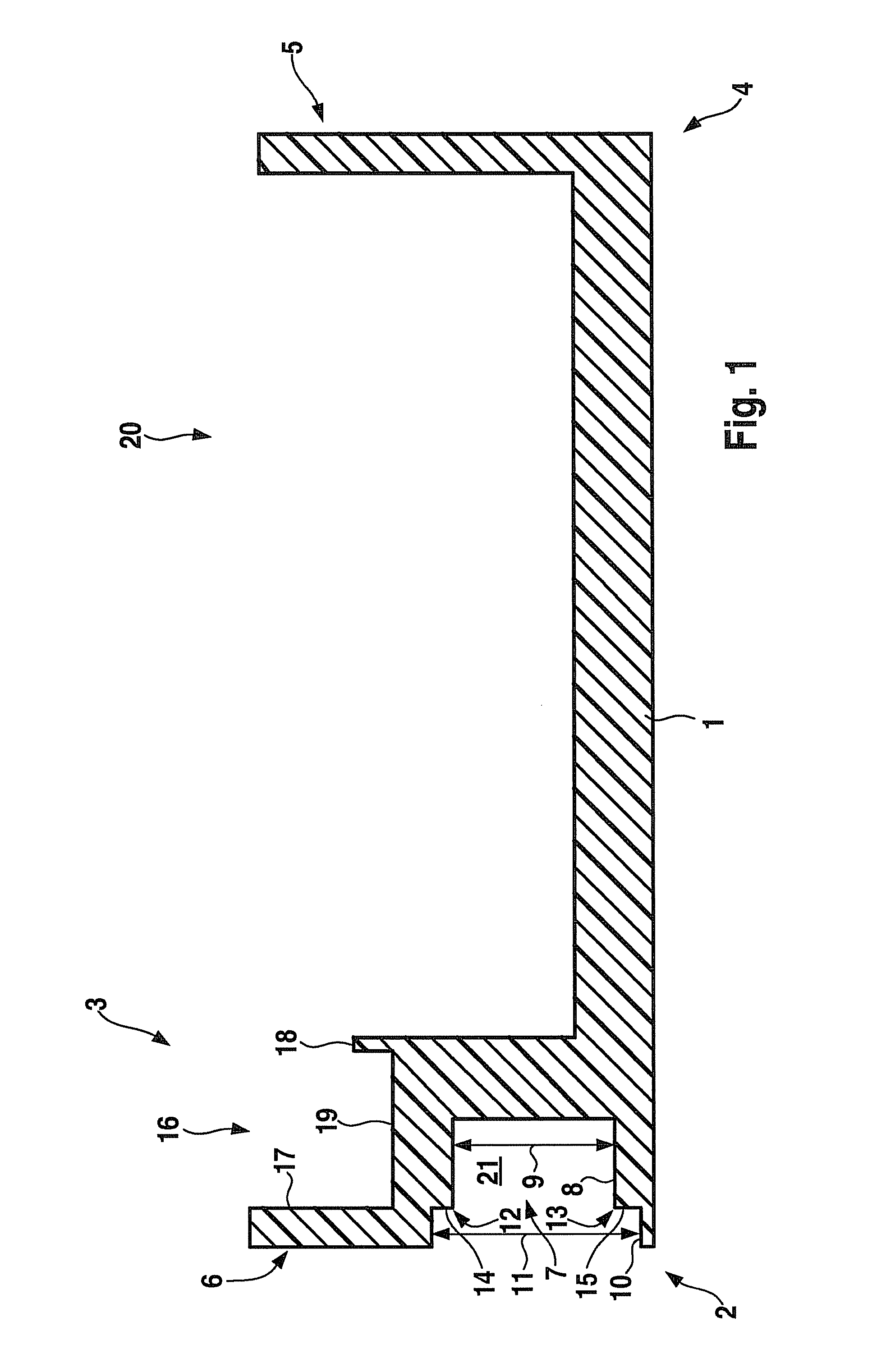
[0030]FIG. 1 shows a sectional representation of an exemplary embodiment of a cylindrical coil brace 1 according to the present invention, of which only the upper part is shown. At its left end 2, coil brace 1 has a first delimitation 3, and at its right end 4 it has a second delimitation 5, delimitations 3, 5 being developed in one piece with coil brace 1. At its side 6 facing away from delimitation 5, delimitation 3 has an axial recess 7 that has a first region 8 having a height 9, and a second region 10 having a height 11, height 11 of outer region 10 being greater than height 9 of inner region 8. Because of the different heights 9, 11, two shoulders 12 and 13 are formed in recess 7, which each have a contact surface 14, 15.

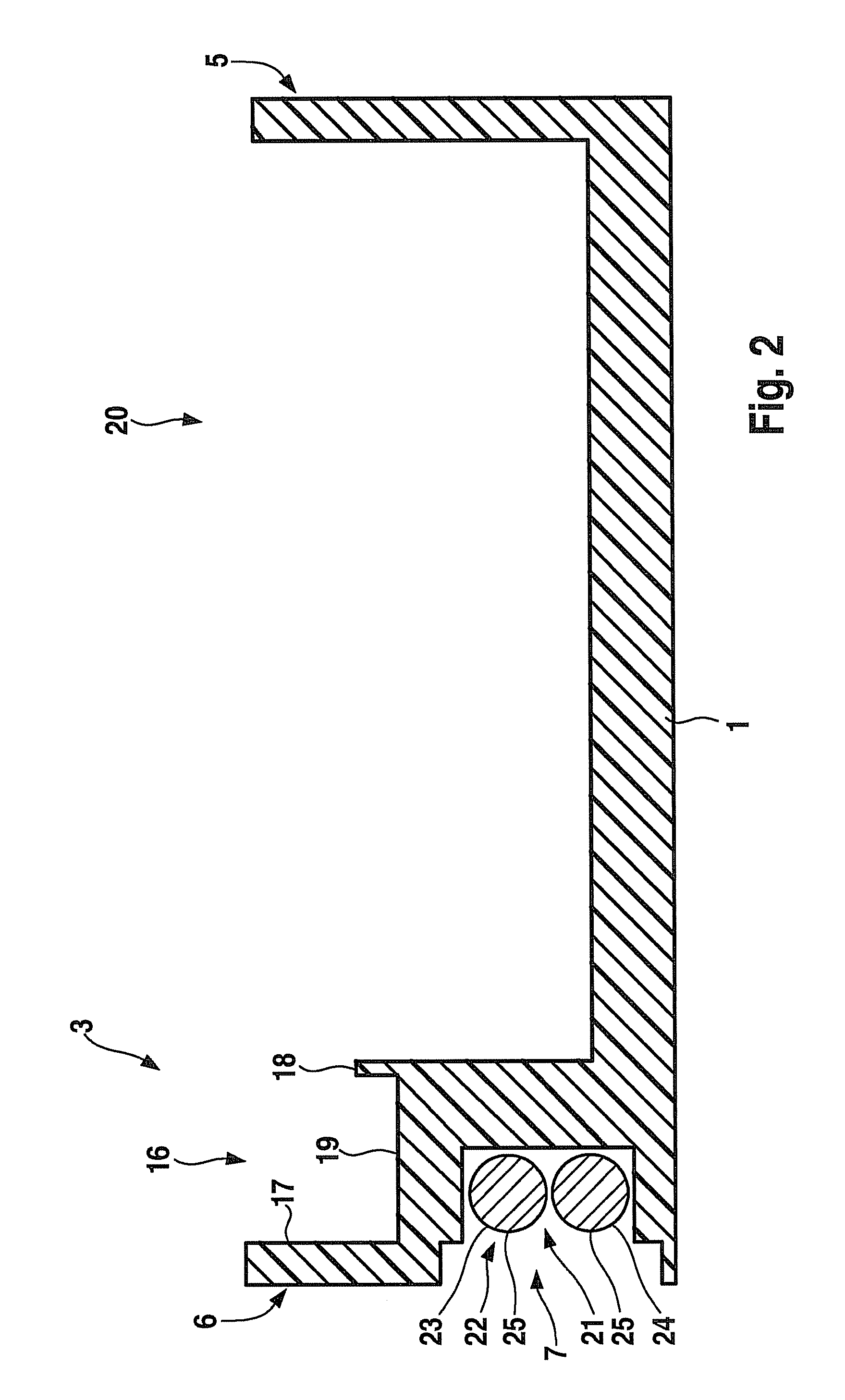
[0031]In addition, delimitation 3 has a radial recess 16, radial recess 16 being partially situated above axial recess 7. Crosspieces 17, 18, that border on radial recess 16, are developed differently, right crosspiece 18 having a lesser height from bottom sur...


PUM

PropertyMeasurementUnit
voltageaaaaaaaaaa
voltageaaaaaaaaaa
currentaaaaaaaaaa

Abstract

A coil configuration having a tube-shaped coil brace of an electromagnetic drive is provided, particularly a two-stage starter solenoid switch, the coil configuration having a holding winding and a pull-in winding. The coil brace has at its one end a first delimitation and at its other end a second delimitation, between which the holding winding is situated. The first delimitation has on its side, facing away from its second delimitation, an axial recess for accommodating the pull-in winding.

Description

BACKGROUND OF THE INVENTION[0001]1. Field of the Invention[0002]The present invention relates to a coil configuration having a tube-shaped coil brace of an electromagnetic drive, particularly a two-stage starter solenoid switch, the coil configuration having a holding winding and a pull-in winding, and the coil brace having at its one end a first delimitation and at its other end a second delimitation, between which the holding winding is situated.[0003]2. Description of Related Art[0004]Coil configurations of the kind described above are known. For instance, there are coil configurations of this type of two-stage starter solenoid switch of internal combustion engine starters which pose high performance and great demands on the service life. The starter solenoid switch is used to push the driving pinion of the starter into a toothed wheel of a transmission or of the internal combustion engine. In the case of single-stage starter solenoid switches, which only effect an axial shifting...

Claims


Application Information

Patent Timeline
Patent Type & Authority Patents(United States)
IPC IPC(8): H01F5/00
CPCF02N15/067H01F5/02H01F7/123H01F7/1607H01H47/04H01H51/065H01F7/1805H01F41/0633H01F41/082
Inventor WANNER, HARTMUT
Owner SEG AUTOMOTIVE GERMANY GMBH
Why Eureka
Try Eureka