Method and an array for magnetizing a magnetizable object

a magnetizable object and array technology, applied in the field of methods and arrays for magnetizing magnetizable objects, can solve the problem that the region at the border between a non-magnetized portion and a magnetized portion of the shaft does not have well-defined magnetic properties, and achieves fast fine-tuning, prevents demagnetization, and high accuracy

Active Publication Date: 2011-08-23
NCTE
View PDF9 Cites 3 Cited by
  • Summary
  • Abstract
  • Description
  • Claims
  • Application Information

AI Technical Summary

Benefits of technology

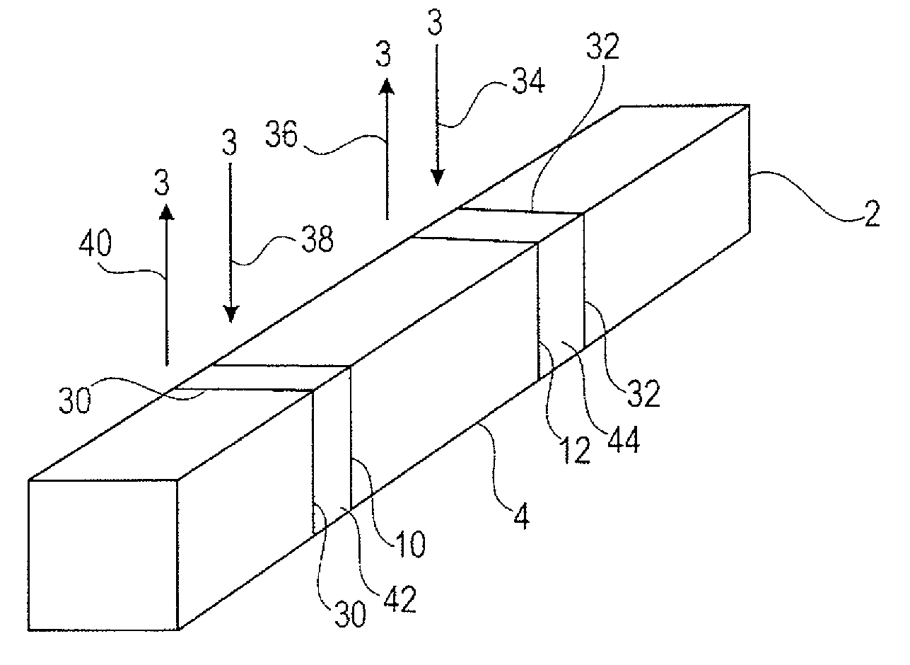
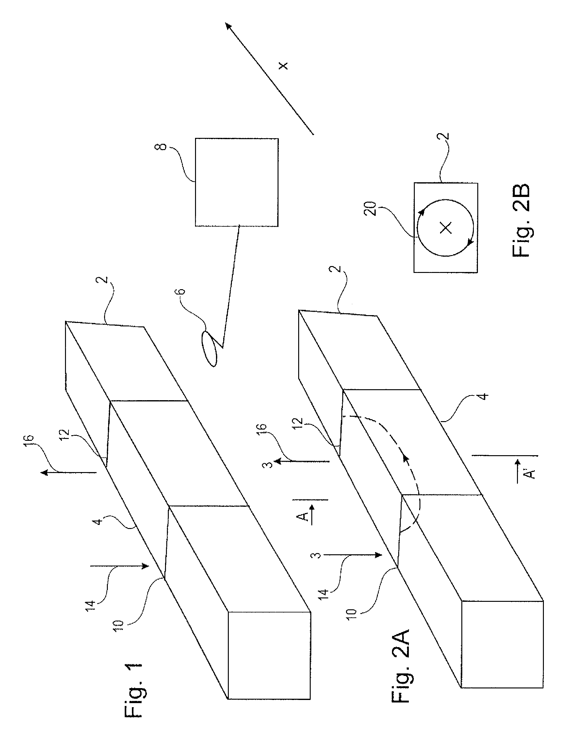
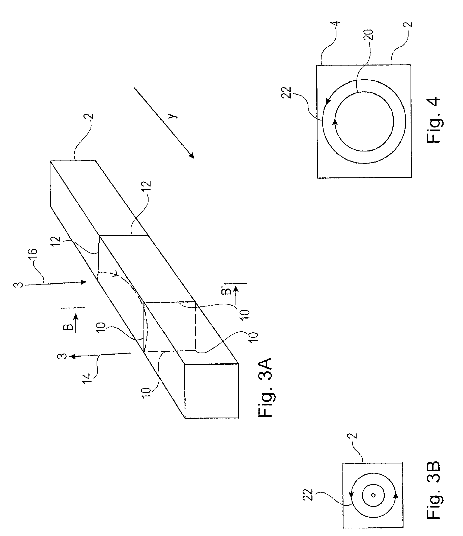
[0010]One idea according to the invention may be seen in the fact that an advantageous magnetization scheme is provided which can be realized with low effort. According to this magnetization scheme, a sequence of different signals may be applied to a magnetizable object to magnetize the same in a defined manner and in a way that parasitic effects are prevented.
[0075]Further, the array of the invention may have a first stopper coil and may have a second stopper coil, the first stopper coil being arranged surrounding a portion of the magnetized portion adjacent the first degaussing coil, and the second stopper coil may be arranged surrounding a portion of the magnetized portion adjacent the second degaussing coil in such a manner that the first and second stopper coils are arranged between the first and second degaussing coils. Such an electrical signal can be applied to the first and the second stopper coils that the region between the first and second stopper coils are prevented from being demagnetized when the degaussing elements are activated. According to this configuration, small stopper coils or stopper inductors may be placed at a specific end of the degaussing elements, and the inductivity of the stopper coils may be significantly lower than the inductivity of the degaussing coils. Thus, the area which is affected by the demagnetization procedure can be defined even better.

Problems solved by technology

However, when a part of a shaft is magnetized in longitudinal direction, as described in WO 02 / 063262, it may happen that a region at the border between a non-magnetized portion and a magnetized portion of the shaft does not have well-defined magnetic properties.

Method used


Image

  • Method and an array for magnetizing a magnetizable object
  • Method and an array for magnetizing a magnetizable object
  • Method and an array for magnetizing a magnetizable object

Examples


first embodiment

[0443]In the following, referring to FIG. 75, an array 800 for adjusting a magnetization of a shaft 100 according to the invention will be described.

[0444]The array 800 for adjusting a magnetization of a magnetizable shaft 100 comprises the shaft 100 having a magnetized portion (not shown) extending along a part of the shaft 100. In the scenario of FIG. 75, the magnetized portion extends along the part of the shaft 100 extending between a first degaussing coil 801 and a second degaussing coil 802. The part of the shaft 100 being magnetized has previously been magnetized according to the PCME technology. A part of the magnetized portion is covered by the coils 801, 802 and will be demagnetized, as described in the following.

[0445]The first degaussing coil 801 is arranged adjacent to the magnetized portion, and the second degaussing coil 802 is arranged adjacent to the magnetized portion. Thus, the shaft 100 has a first unmagnetized portion and a second unmagnetized portion, the magne...

second embodiment

[0453]In the following, referring to FIG. 76, an array 900 for adjusting a magnetization of the shaft 100 according to the invention will be described, which is further improved compared to the embodiment shown in FIG. 75.

[0454]According to FIG. 76, only one of the coils 801, 802 at one time is connected to the alternating electrical current. In other words, according to FIG. 76, a first voltage may be applied between the first connection 803 and the second connection 804 of the first degaussing coil 801, and independently from this, a second voltage may be applied between the first connection 805 and the second connection 806 of the second degaussing coil 802, one voltage being applied after the other.

[0455]As can be seen from the graph in FIG. 76, the field cancellation efficiency is significantly reduced in the area between the coils 801, 802 compared to the array 800, so that the portion related to the remaining magnetization in the center of shaft 100 is prevented from being de...

third embodiment

[0457]In the following, referring to FIG. 77A, an array 1000 for adjusting a magnetization of the shaft 100 according to the invention will be described.

[0458]According to the embodiment shown in FIG. 77A, the array has a first stopper coil 1001 and has a second stopper coil 1002, the first stopper coil 1001 being arranged surrounding a portion of the magnetized portion adjacent the first degaussing coil 801, and the second stopper coil 1002 is arranged surrounding a portion of the magnetized portion adjacent the second degaussing coil 802 in such a manner that the first and second stopper coils 1001, 1002 are arranged between (intermediate, i.e. sandwiched between) the first and second degaussing coils 801, 802, wherein such a voltage can be applied to the first and second stopper coils 1001, 1002 that the region between the first and second stopper coils 1001, 1002 is prevented from being demagnetized when the degaussing elements 801, 802 are magnetized.

[0459]As can be seen in FIG...


PUM


Abstract

Described is a method and array for magnetizing a magnetizable object. The method includes the steps of (a) applying a first degaussing signal to the magnetizable object to degauss the magnetizable object and the first degaussing signal is an alternating electrical signal having a first frequency and a first amplitude; (b) applying a magnetizing signal to the degaussed magnetizable object to magnetize the magnetizable object; and (c) applying a second degaussing signal to the magnetized magnetizable object to partially degauss the magnetized magnetizable object and the second degaussing signal is an alternating electrical signal having a second frequency and a second amplitude.

Description

FIELD OF THE INVENTION[0001]The present invention relates to a method and an array for magnetizing a magnetizable object.DESCRIPTION OF THE RELATED ART[0002]Magnetic transducer technology finds application in the measurement of torque and position. It has been especially developed for the non-contacting measurement of torque in a shaft or any other part being subject to torque or linear motion. A rotating or reciprocating element can be provided with a magnetized region, i.e. a magnetic encoded region, and when the shaft is rotated or reciprocated, such a magnetic encoded region generates a characteristic signal in a magnetic field detector (like a magnetic coil) enabling to determine torque or position of the shaft.[0003]For such kind of sensors which are disclosed, for instance, in WO 02 / 063262, it is important to have a magnetically encoded region extending along a spatially accurately defined portion of the shaft. However, when a part of a shaft is magnetized in longitudinal dir...

Claims


Application Information

Patent Timeline
Patent Type & Authority Patents(United States)
IPC IPC(8): H01H47/00
CPCH01F13/00
Inventor MAY, LUTZ
Owner NCTE
Why Eureka
Try Eureka