Method and apparatus to remove energy from DC loads

a technology of dc load and energy removal, applied in the direction of electrical equipment, power conversion systems, instruments, etc., can solve the problems of increasing the energy loss of the system, requiring additional expense and complexity on the part of the user, and storing energy within the load(s) to dissipate passively,

Active Publication Date: 2011-08-23
TEKNIC
View PDF14 Cites 156 Cited by
  • Summary
  • Abstract
  • Description
  • Claims
  • Application Information

AI Technical Summary

Problems solved by technology

When power is removed to these devices or the device is commanded to turn off, stored energy within their load(s) dissipates passively due to energy consumption or other parasitic losses within the load.
These techniques require additional expense and complexity on the part of the user and / or add to the system energy losses while operating.

Method used


Image

  • Method and apparatus to remove energy from DC loads
  • Method and apparatus to remove energy from DC loads
  • Method and apparatus to remove energy from DC loads

Examples


first example

AC-DC Converter

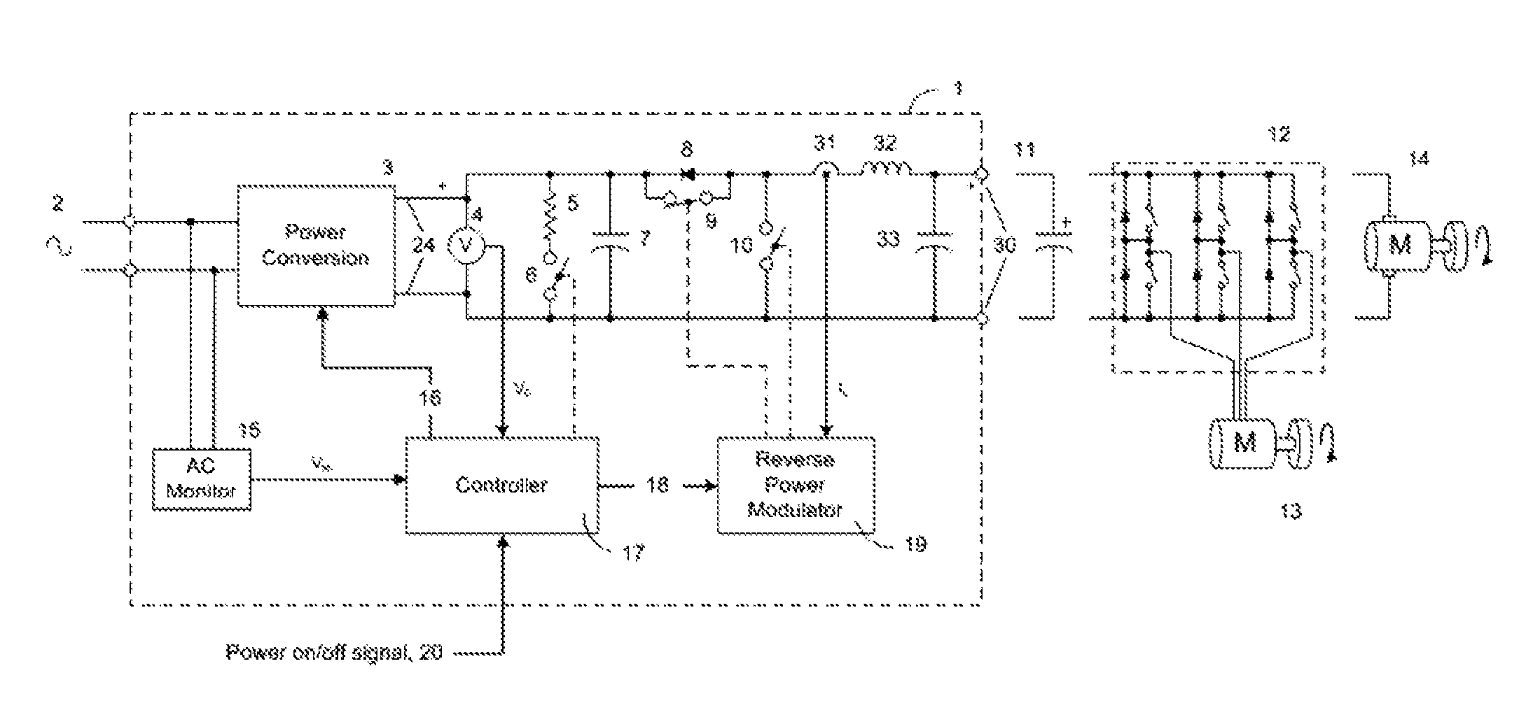
[0022]FIG. 1 illustrates an AC-DC converter embodying the invention (1) which applies all three methods of load energy removal for purposes of example. It will be understood by one skilled in the art that the invention need not necessarily include all three methods, but may incorporate one, two or all of the methods as desired.

[0023]AC power (2) is applied to power converter stage (3), which converts the AC power to DC at DC supply points (24). The AC power input (2) may be monitored by an AC monitor (15), which measures the voltage (2) and supplies a signal VAC representing the status of the AC input (2) to an input of controller (17).

[0024]The power converter (3) has a control input (16) coupled to an output of controller (17), which allows the controller (17) to switch the converter (3) on or off. This converter (3) could be any power supply known to the art, ranging from a simple rectifier to a regulated DC power supply or a switching power supply.

[0025]The DC out...

second example

DC Power Switch

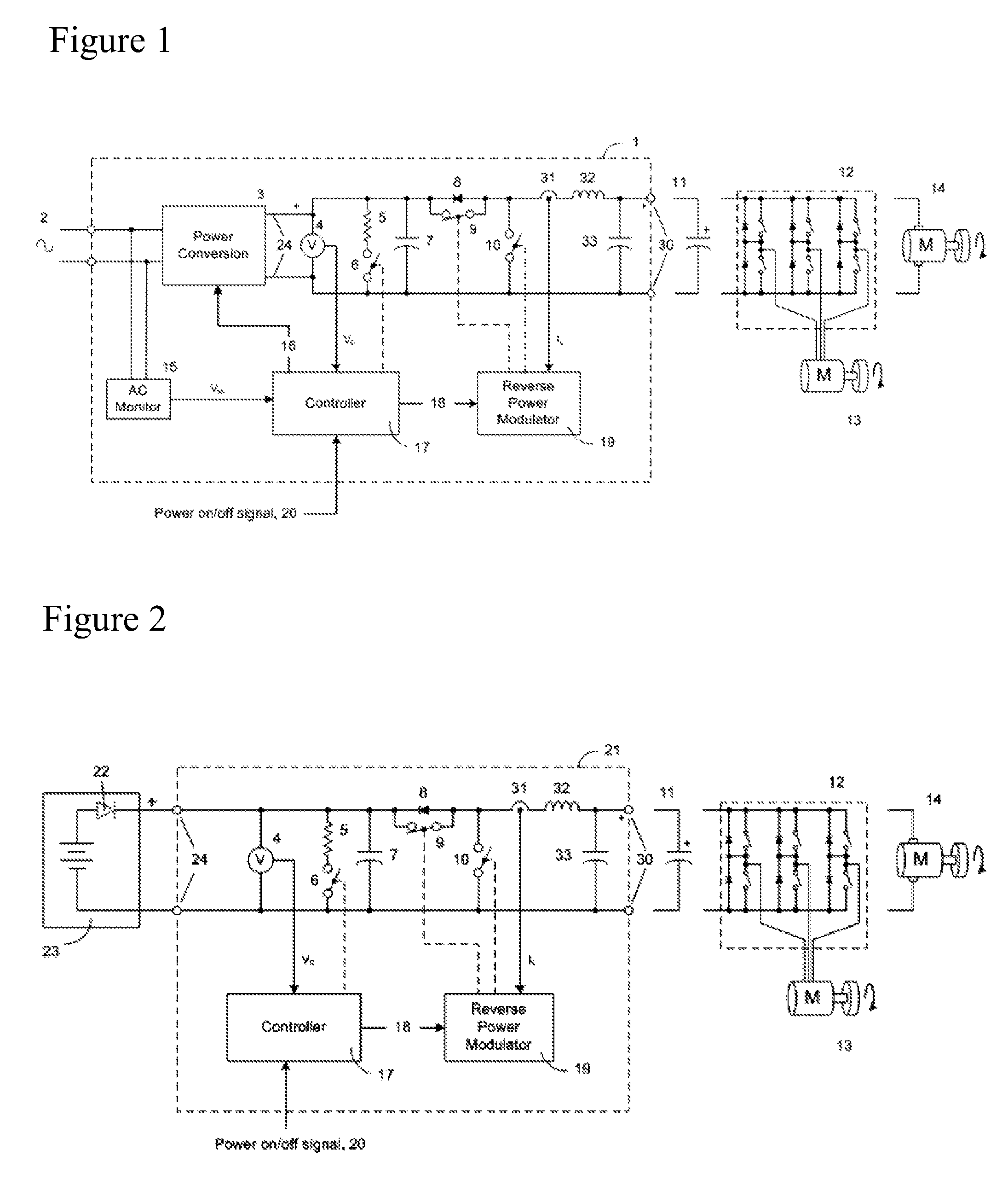
[0032]FIG. 2 illustrates a simpler embodiment of the invention which is useful where a source of DC exists at the correct voltage and with sufficient current capability to power a DC load without having to convert it from AC.

[0033]In this example, the power converter (3) and AC monitor (15) of FIG. 1 are omitted, and the circuit of the invention (21) is directly supplied by DC (24) from an external DC supply (23). This DC supply could be, for example, a battery (as shown schematically in the figure), a rectifier, an external regulated power supply or switching supply fed from the AC line, a generator, or any other DC power source known to the art.

[0034]If the DC supply (23) is of a kind which cannot accept reverse current, a blocking diode (22) may optionally be provided.

[0035]The other elements of the circuit (21) are the same as described the circuit (1) of the first example, above, and will not be separately described herein. Elements in FIG. 2 which are the same a...


PUM


Abstract

A DC output power converter or DC switch device that includes methods and apparatus to reverse the current in the connected load, thereby draining the load's energy until the voltage in the load is brought to a (near) zero potential and held there.

Description

REFERENCE TO RELATED APPLICATIONS[0001]This application claims one or more inventions which were disclosed in Provisional Application No. 61 / 018,726, filed Jan. 3, 2008, entitled “Method and Apparatus to Remove Energy from DC Loads”. The benefit under 35 USC §119(e) of the United States provisional application is hereby claimed, and the aforementioned application is hereby incorporated herein by reference.BACKGROUND OF THE INVENTION[0002]1. Field of the Invention[0003]The invention pertains to the field of DC power supplies. More particularly, the invention pertains to methods and apparatus for control of loads on DC power supplies.[0004]2. Description of Related Art[0005]In many electrical systems DC power is applied to a load (or loads) by a DC output power converter or a DC switch at the assertion of an on-off control signal or simply by applying power to the input of the DC switch or the DC output power converter. When power is removed to these devices or the device is commanded...

Claims


Application Information

Patent Timeline
Patent Type & Authority Patents(United States)
IPC IPC(8): H02M7/10
CPCH02M1/36
Inventor BUCELLA, THOMAS JOHNDOMBROSKI, THOMAS P.FUCHS, DAVID E.BLOCK, JEREMY M.
Owner TEKNIC
Why Eureka
Try Eureka