Data path differentiator for pre-emphasis requirement determination or slot identification

a data path and requirement technology, applied in the field of communication, can solve the problems of inability to accurately transmit data with acceptable error rates, inefficient space, power, cooling and other characteristics, transmission errors and unacceptable error rates,

Inactive Publication Date: 2011-08-23
AVAGO TECH INT SALES PTE LTD
View PDF10 Cites 5 Cited by
  • Summary
  • Abstract
  • Description
  • Claims
  • Application Information

AI Technical Summary

Benefits of technology

[0018]In the embodiment mentioned above in which the path length information generating circuit will give an indication as to whether the receiving device is inserted near the center of the midplane (or any location in the range of slot locations as identified by a threshold value) and which paths are the longer and shorter paths, the high impedance elements feed a differential amplifier for each data path to bring the signal to a usable level and to convert it into a single ended signal, thereby simplifying and reducing requirements for further stages. These amplifiers will typically have the same gain or amplification level.
[0024]Once the longer and shorter path determination and the relative position determination has been made, this information may be converted to a digital value using an Analog to Digital (A / D) converter and can be used by hardware and / or a processor to set pre-emphasis settings for transmitters in the return paths of the receiving device (which may be the same as the receive path lengths), and / or equalizer settings for the receive path equalizers. Alternatively, instead of providing the relative position determination (output of the second comparator) to the hardware or processor, the output of the differential amplifier may be converted using an A / D converter and provided to the hardware or processor for making the relative position determination and pre-emphasis settings. This embodiment does not enable perfect equalization / pre-emphasis, but provides an approximate indication of where the receiving device is plugged into the midplane so the hardware and / or processor can set the equalization with some level of intelligence.

Problems solved by technology

Blade servers overcome some of the inefficiencies of individual standalone or rack-mounted One Unit (1U) high servers, each of which is self-contained and includes separate power supplies, fans, and the like, and are therefore inefficient in terms of space, power, cooling, and other characteristics.
These differences may cause transmission errors and unacceptable error rates, among other things.
However, because frequencies and data rates have increased, resulting in higher signal attenuation, especially at the upper (higher) frequencies of the data signal (and hence more deterministic jitter), conventional modern systems may employ transmitter circuits with pre-emphasis on their transmit outputs in an attempt to transmit data with an enhanced frequency response in order to receive a flat frequency response at the far or “receiving” end, and achieve acceptable bit error rates.
Because of the rolloff of the amplifier at high frequencies, the eye in the time domain closes at those frequencies, and data can no longer be accurately transmitted with acceptable error rates, if at all.
However, even though the true definition of pre-emphasis is boosting of the higher frequencies, the transmit amplifier is limited by its supply voltages.
Without slot identification, it is difficult to determine the proper pre-emphasis and / or equalization settings for the path loss (link budget) at the faster data rates.
Too much pre-emphasis or equalization will have the same effect as too little pre-emphasis or equalization, resulting in a higher bit error rate and less than optimized performance.
The former approach is often not practical, and the latter approach may result in some slots having overdriven signals and others having underdriven signals, resulting in unacceptable error rates and the need for complicated gain control circuitry.

Method used


Image

  • Data path differentiator for pre-emphasis requirement determination or slot identification
  • Data path differentiator for pre-emphasis requirement determination or slot identification
  • Data path differentiator for pre-emphasis requirement determination or slot identification

Examples


Embodiment Construction

[0034]In the following description of preferred embodiments, reference is made to the accompanying drawings which form a part hereof, and in which it is shown by way of illustration specific embodiments in which the invention may be practiced. It is to be understood that other embodiments may be utilized and structural changes may be made without departing from the scope of the preferred embodiments of the present invention.

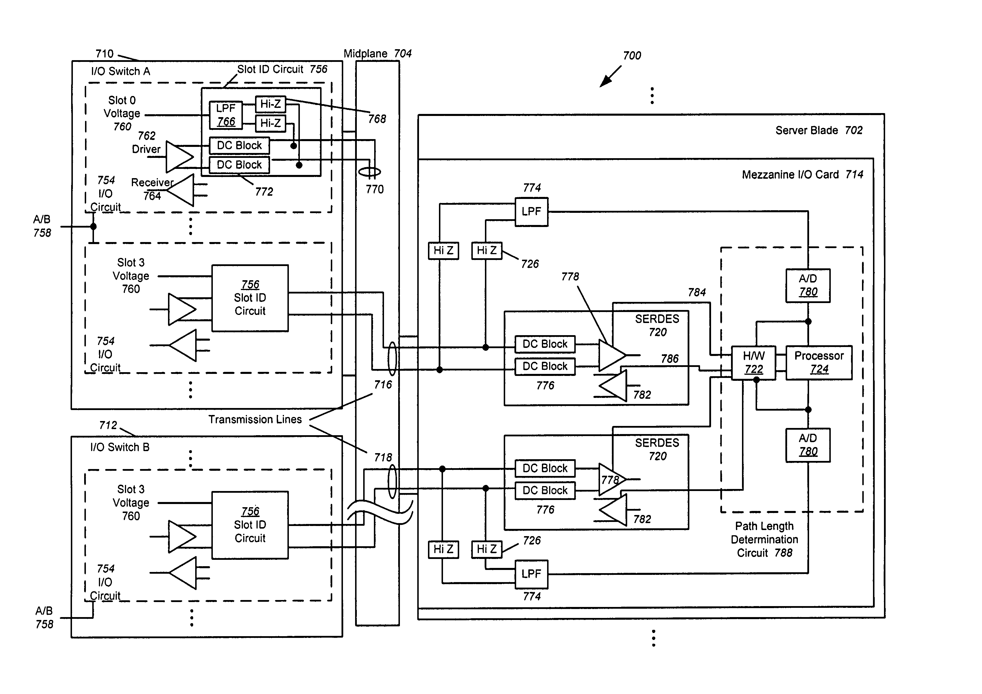
[0035]Although embodiments of the present invention may be described herein primarily in terms of FC signaling, it should be understood that the present invention is not limited to FC, but includes InfiniBand, Ethernet, Serial Attached Small Computer System Interconnect (SAS), Serial ATA (SATA) signaling and the like. Implementation of these protocols requires that the midplane support the protocol.

[0036]FIG. 4 is an illustration of an exemplary blade server 400 with multiple server blades 402, each server blade including a controller, host interface card, HBA, o...


PUM


Abstract

An apparatus and method is disclosed for generating path length information for two (usually redundant) receive paths in a receiving device such as a server blade so that the proper amount of equalization and / or pre-emphasis may be applied to receiver and driver circuits in the server blade. In one embodiment, the path length information comprises a longer or shorter path determination, and may also include a estimation of the slot location. In another embodiment, the path length information comprises a representation of the length of two receive paths. The path length information generating circuit is connected to the two receive inputs of the receiving device though high impedance elements, and the path length information may be utilized by hardware or a processor to set the equalization or pre-emphasis in the receiver and / or driver.

Description

FIELD OF THE INVENTION[0001]This invention relates to communications between devices within blade servers, and more particularly in one embodiment, to an apparatus for automatically identifying and / or estimating the lengths of data paths between redundant interface devices and one or more Input / Output Controllers (IOCs) within the blade server to assist in equalizing the frequency response of those data paths.BACKGROUND OF THE INVENTION[0002]FIG. 1 is an illustration of an exemplary conventional blade server 100 connected to an external switched fabric 108. Blade servers overcome some of the inefficiencies of individual standalone or rack-mounted One Unit (1U) high servers, each of which is self-contained and includes separate power supplies, fans, and the like, and are therefore inefficient in terms of space, power, cooling, and other characteristics. Blade servers 100 utilize a modular, plug-in approach wherein the housing for each server is eliminated along with self-contained co...

Claims


Application Information

Patent Timeline
Patent Type & Authority Patents(United States)
IPC IPC(8): G01R31/08
CPCG06F11/2005G06F11/2007G06F13/4022G06F11/2012G06F11/2015
Inventor JOVANOVICH, ALAN FRANKHOLNESS, STEPHEN EUGENE
Owner AVAGO TECH INT SALES PTE LTD
Why Eureka
Try Eureka