Bi-directional optical module with improved optical crosstalk

a bi-directional optical module and optical crosstalk technology, applied in the direction of optical elements, multiplex communication, instruments, etc., can solve the problem of cost-demort for two-package modules, and achieve the effect of improving the optical crosstalk performance of bi-directional modules

Active Publication Date: 2011-08-23
SUMITOMO ELECTRIC IND LTD
View PDF6 Cites 13 Cited by
  • Summary
  • Abstract
  • Description
  • Claims
  • Application Information

AI Technical Summary

Benefits of technology

[0012]The optical module of the present invention, because the WDM filter in the edge surface thereof has the obtusely angle to the primary surface thereof, the light reaching this edge and reflected thereat is prevented from coupling with the PD, which enhances the optical crosstalk performance of the bi-directional module.

Problems solved by technology

However, this two-package module follows a cost-demerit because it applies two can packages for the TOSA and the ROSA even the packages are popular and available in the market.
The one-package module mentioned above is able to miniaturize the whole body, but has a weak point to degrade the crosstalk where the transmitting light emitted from the LD is diffusely reflected by the WDM filter to cause the stray and the PD receives this stray light.

Method used


Image

  • Bi-directional optical module with improved optical crosstalk
  • Bi-directional optical module with improved optical crosstalk
  • Bi-directional optical module with improved optical crosstalk

Examples


Embodiment Construction

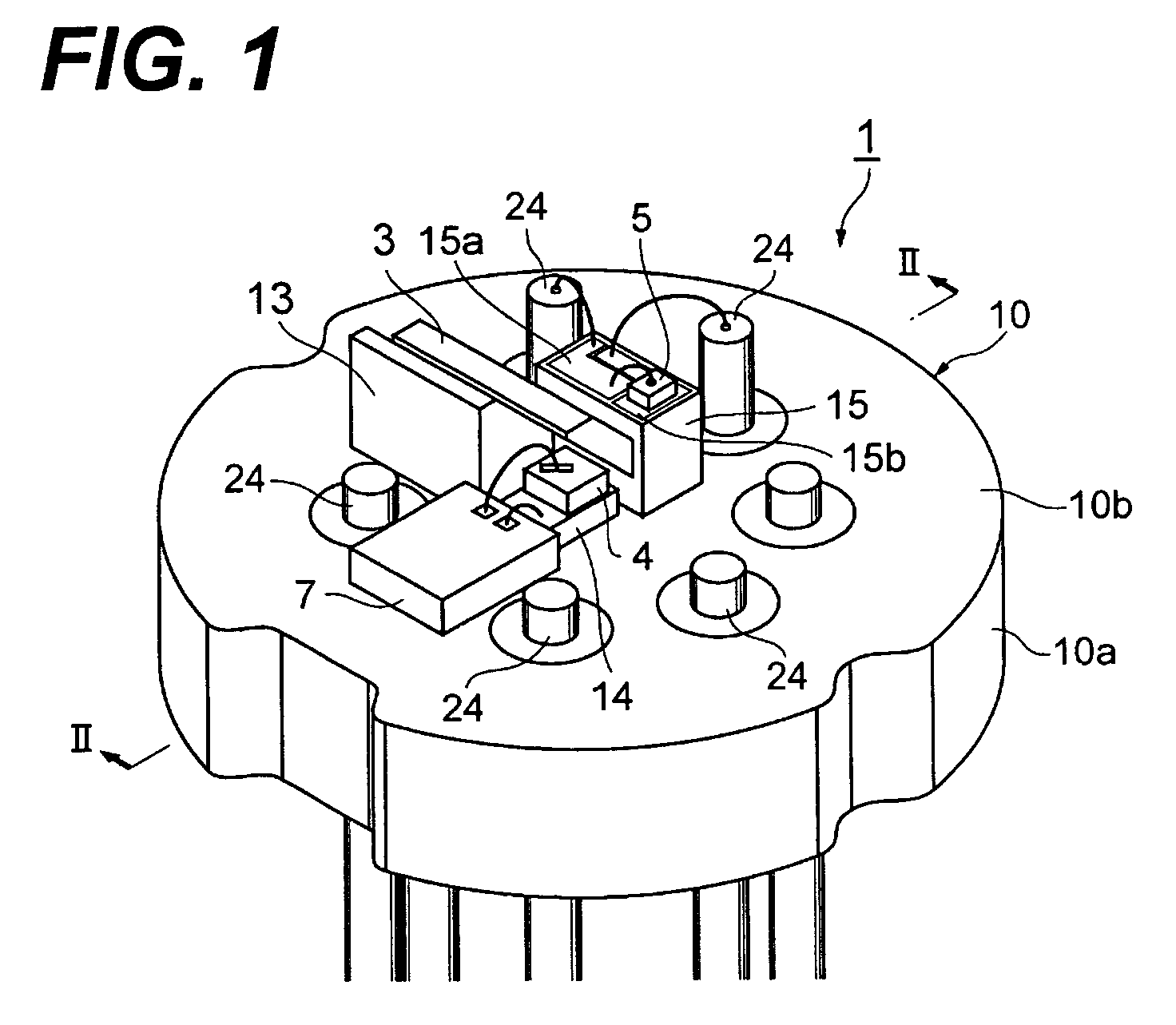
[0017]FIG. 1 is a perspective view showing an inside of an optical module 1 according to the present invention. The optical module 1 includes, on a primary surface 10b of a disk-shaped stem 19, both photodiode (PD) 4 as a light-receiving device and laser diode (LD) 5 as a light-transmitting device and a WDM filter 3 arranged between these devices.

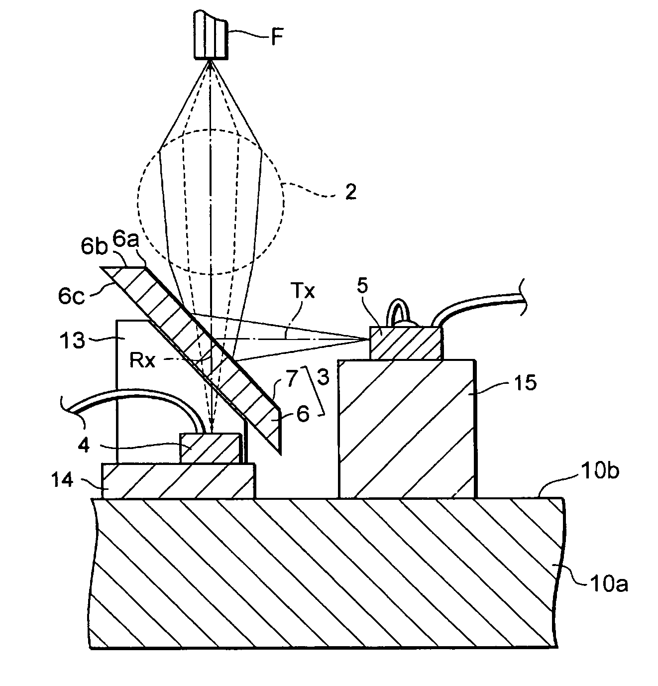
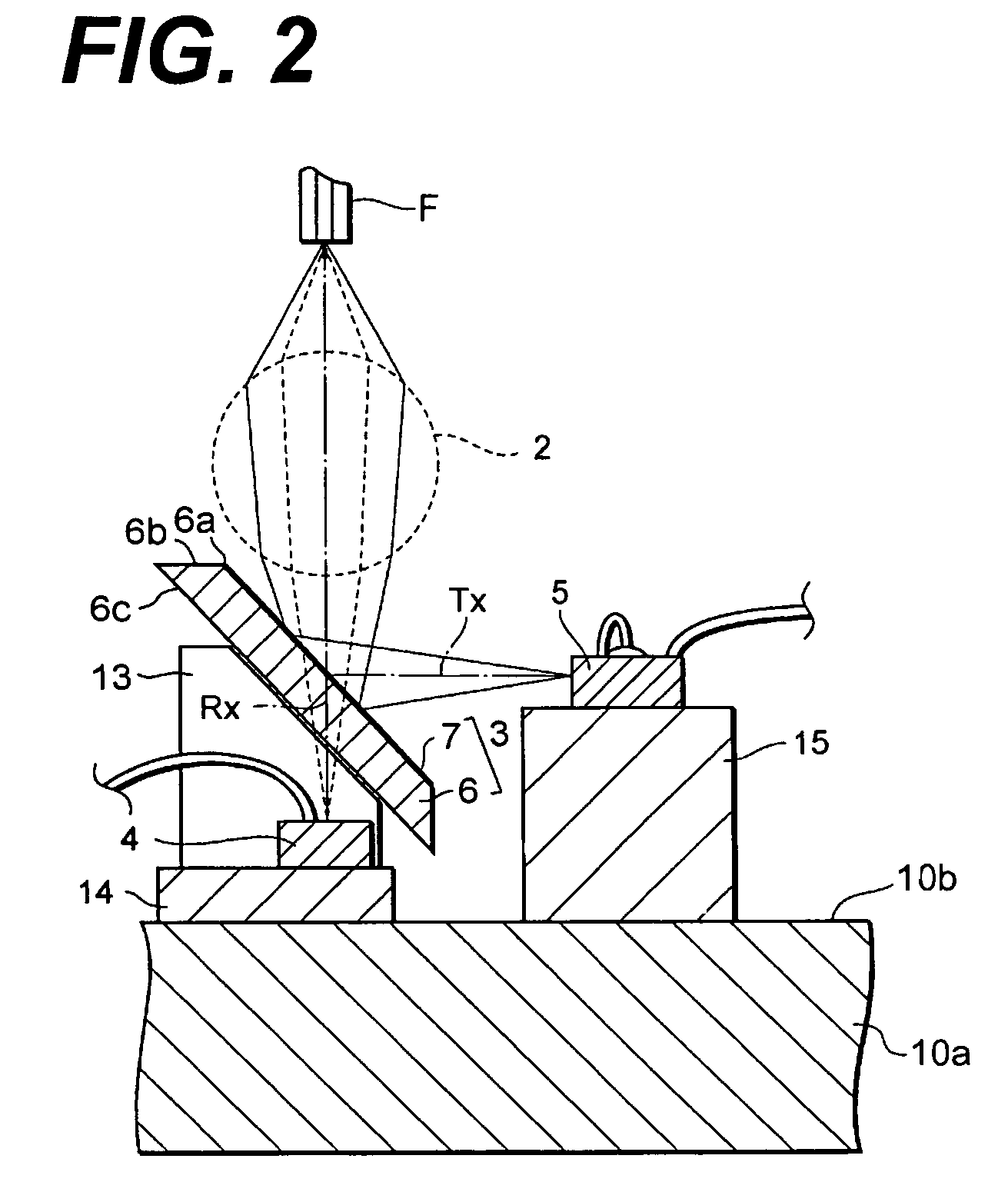
[0018]An optical arrangement of the module 1 will be described as referring to FIG. 2. The light emitted from the LD with a wavelength of λ1 advances on the optical axis Tx of the LD and is reflected by a multi-layered optical film 7 formed on the surface of the WDM filter 3. The light bent whose axis Tx is bent by 90° by the WDM filter 3 advances upward, and is concentrated on the end of the single mode fiber (SMF) F by the lens 2.

[0019]While, the light provided from the end of the fiber F, whose wavelength is λ2 different from λ1, is concentrated by the lens 2, passing through the WDM filter 3 and advances to the PD 4 arranged below the W...


PUM


Abstract

The bi-directional optical module, which installs the receiver and the transmitter within one package, is disclosed with an improved optical crosstalk. The optical module provides a lens, a WDM filter and a photodiode (PD) on an axis of the single mode fiber coupled with the module, while, a laser diode (LD) in a position perpendicular to the optical axis. The WDM filter provides a multi-layered optical film on a primary surface and an edge in a side far from the LD and the (PD) makes an obtuse angle to the primary surface so as to prevent light from the LD and reflected at this edge from entering the PD.

Description

BACKGROUND OF THE INVENTION[0001]1. Field of the Invention[0002]The present invention relates to a bidirectional optical module for the signal optical fiber which includes a wavelength division multiplexed (WDM) filter.[0003]2. Related Prior Arts[0004]The PON (Passive Optical Network) system has been introduced in the network system between the center and the subscribers, which is typically realized in the FTTH (Fiber to the Home) and provides higher speed and larger capacity communication with a reasonable cost. The PON system implements optical couplers in the communication line to draw the fiber into a plurality of users, which is equivalent to a system where the plurality of users shares the single fiber connected to the center station. The PON system may reduce the count of optical fibers pulled out from the center station, thus, realizes the advanced communication service with higher speed with reduced cost comparable to that using the metal cable. Further, the PON system is o...

Claims


Application Information

Patent Timeline
Patent Type & Authority Patents(United States)
IPC IPC(8): H04B10/12G02B6/42H01L31/0232H01L33/48
CPCG02B6/4246H04J14/02H01L2224/48091H01L2224/48137H01L2924/00014
Inventor NAKANISHI, HIROMIKIHARA, TOSHIAKI
Owner SUMITOMO ELECTRIC IND LTD
Why Eureka
Try Eureka