Method and device for controlling a drive system

a technology of drive system and control device, which is applied in the direction of driving system input parameters, computation using non-denominational number representation, analog and hybrid computing, etc., can solve the problems of insufficient traction, corresponding traction problems, and instabilities so as to improve the control of the drive system, reduce the wheel, and increase the drive efficiency

Inactive Publication Date: 2011-08-23
LIEBHERR WERK NENZING
View PDF7 Cites 1 Cited by
  • Summary
  • Abstract
  • Description
  • Claims
  • Application Information

AI Technical Summary

Benefits of technology

[0004]Proceeding therefrom, it is the object underlying the present invention to create an improved method and an improved device for controlling a drive system as mentioned above, which avoid the disadvantages of the prior art and develop the latter in an advantageous way. Preferably, an improved drive control should be created, which increases the efficiency of the drive, reduces wheel wear, and increases traction.
[0006]Thus, a control is proposed on the one hand, which effects an intelligent differential lock between a left drive wheel and a right drive wheel, which even during cornering prevents the driven wheels from being strained against each other and nevertheless ensures a speed coupling of the two wheels even in the case of traction problems. On the other hand, a control is proposed in accordance with a further aspect of the invention, which reliably prevents or limits a slip of a drive wheel or element and thereby increases the efficiency of the drive and reduces wear. In accordance with a first aspect of the present invention, the specified power limit value, in dependence on which the at least one actuating signal is provided for the at least one drive unit, is reduced in dependence on a matching of the specified desired value of the output parameter with a current actual value of said output parameter. If the difference between desired value and actual value of the output parameter exceeds a predetermined tolerance threshold, the power limit value is reduced correspondingly, whereby the actuating signal is corrected correspondingly.
[0007]In particular, said output parameter can be an output speed of the drive unit and thus a wheel speed, when the element to be driven is a traveling gear wheel. A traveling gear wheel can be a wheel rolling directly on the ground, when a wheel drive is provided. However, the traveling gear wheel can also be a drive wheel or pinion, over which runs a drive chain. Thus, when the difference between the desired speed and the actual speed of the respective drive wheel lies above an admitted tolerance value, the power limit value is reduced correspondingly, in order to correspondingly reduce the actuating signal for the drive unit. Slip can thus be prevented. Slip prevention can be achieved both during acceleration and during braking, in that as a power limit value a maximum power value for the power to be provided on the one hand and a maximum power value for the power to be recirculated on the other hand is reduced as described above in dependence on the matching between desired value and actual value of the output parameter.
[0012]Alternatively or in addition to the determination of the desired value of the output parameter of the one drive unit in dependence on the actual value of the corresponding output parameter of the other drive unit, said desired value can also be determined in dependence on sensor signals which in particular represent the speed of the equipment driven by the respective drive element. In particular, said desired value of the output parameter of the drive unit to be controlled can be determined in dependence on the actual traveling speed, which in accordance with a development of the invention can be determined via a speed sensor on a non-driven wheel and / or an acceleration sensor and / or another velocity sensor. In this way it can be checked whether all the elements to be driven have a slip, in particular whether the entire vehicle is skidding. In particular, the special case of a bilateral blockage of both drive systems or of a bilateral spinning of both wheels can be detected therewith. If this is the case, the corresponding power specification for both drive units can be reduced simultaneously. Thus, both or all drive units are decelerated or accelerated automatically, in order to reach the substantially slip-free and hence efficient working range.
[0013]To achieve an optimum traction for cornering, it is provided in accordance with a further aspect of the present invention that in dependence on a steering angle for each wheel to be driven or for the associated drive unit a separate desired speed is specified and in dependence on the separate desired speeds for each drive unit separate actuating signals are provided. In this way, a rigid coupling of the drive wheels of the right side with the drive wheels of the left side can be enforced without achieving that the drive wheels are strained against each other. The inventive idea consists in that as a result of a known steering angle of the steering wheel or the steering wheels, the geometrical relations for correct cornering can be resolved and hence the required wheel speeds on the two driving wheels definitely can be calculated in advance and thus the corresponding desired speeds for the control circuits of the drive units can be specified. When driving straight ahead, both wheels must be driven with the same speed, whereas during cornering the outside wheel must be driven at a corresponding faster rate than the inside wheel. In both cases, desired speeds for the drive units on the right and on the left definitely are impressed, so that the right and left wheels in principle are coupled with each other like by a differential lock. If one of the two drive wheels would spin, for instance because the ground becomes too smooth to transmit the drive power, the drive power thereof is adjusted downward, as a fixed desired speed is specified. In dependence on the steering angle, a fixed ratio between the desired speed of the left and right wheels is specified. This cannot result in an excessive slip on grounds with poor adhesion, either an inadmissible increase in speed as a result of an excessive drive power or an insufficient speed as a result of an excessive braking power.
[0017]In accordance with an advantageous embodiment of the invention, the actuating signals for the hydraulic components of the hydraulic circuit are limited or reduced both in dependence on a specified power value for the power provided by the system and in dependence on a specified power value for the power recirculated into the system. In particular, the actuating signal can be limited and / or reduced on the one hand in dependence on a matching of the current pump power value with a specified maximum power value for the power to be provided and on the other hand in dependence on a matching of the current motor power value with a specified maximum power value for the power to be recirculated. This can ensure on the one hand that the power provided by the hydraulic circuit does not overshoot the mark, while it is achieved on the other hand that the braking torque provided by the hydraulic circuit is in correspondence with the power specifications provided therefor.

Problems solved by technology

On the other hand, operating the actuators too fast or overriding the same can lead to instabilities of the drive system.
Construction machines such as cranes, caterpillars and the like, which can have a wheel drive or also a chain drive, regularly are moved on grounds such as gravel tracks, loamy or gravelly grounds or generally soil without surface coating, which often involve an only insufficient traction.
This involves the corresponding traction problems during acceleration and braking.
However, this in turn involves problems during cornering, in particular on grounds with higher traction.
The slip induced by differential locks leads to premature wear both of the driveable pavement and of the corresponding drive elements.

Method used


Image

  • Method and device for controlling a drive system
  • Method and device for controlling a drive system
  • Method and device for controlling a drive system

Examples


Embodiment Construction

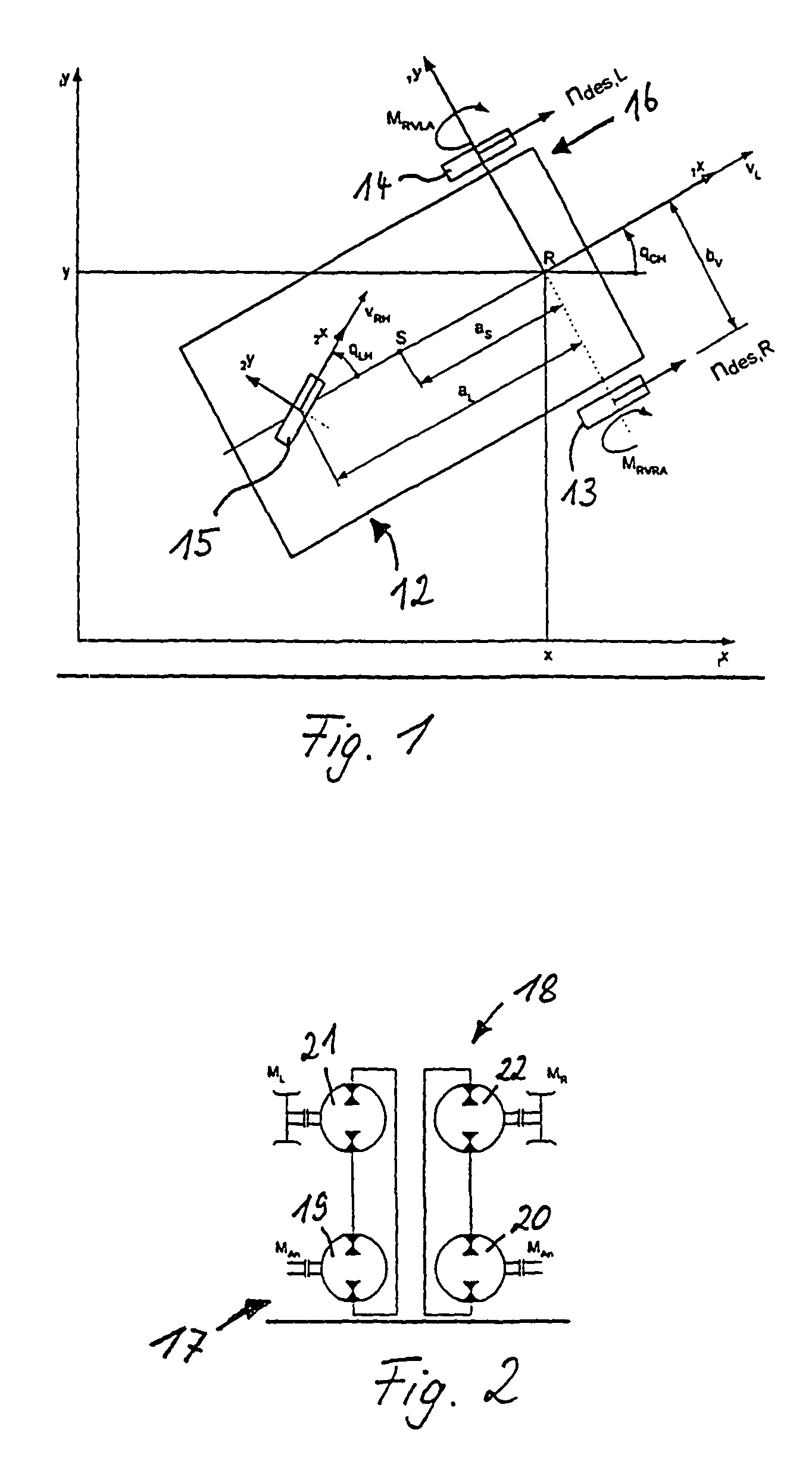
[0028]FIG. 1 shows an industrial truck 12 in the form of a three-wheel fork lift truck, which has a right driven wheel 13 and a left driven wheel 14 as well as a steerable third wheel 15. It is to be understood that the invention can, however, also be implemented in other construction machines, such as cranes, caterpillars or the like, in particular that instead of the illustrated wheeled traveling gear 16 a tracked traveling gear or the like can also be provided.

[0029]On the left and right front drive sides, the vehicle 12 as shown in FIG. 1 is driven separately by independent drive units 17 and 18, which advantageously can each constitute closed hydraulic circuits with one hydraulic pump 19, 20 and one hydraulic motor 21, 22 each, as shown in FIG. 2. Advantageously, the hydraulic pumps 19 and 20 can be driven by a common drive unit, preferably in the form of an internal combustion engine.

[0030]As shown in FIG. 1, the geometry for correct cornering can be resolved on the basis of a...


PUM


Abstract

The present invention generally relates to a method and a device for controlling a drive system, in particular a hydraulic traveling drive of a crane, a caterpillar, an industrial truck or a construction machine, which has at least one drive unit for an element to be driven. The invention relates to a control device for controlling such drive system, comprising a control signal circuit for providing an actuating signal for adjusting the at least one drive unit in dependence on a specified desired value of an output parameter as well as a specified power limit value for the at least one drive unit.

Description

BACKGROUND OF THE INVENTION[0001]The present invention generally relates to a method and a device for controlling a drive system, in particular a hydraulic traveling drive of a crane, a caterpillar, an industrial truck or a construction machine, which has at least one drive unit for an element to be driven. On the one hand, the invention relates to a method, in which a desired value of an output parameter as well as a power limit value for the at least one drive unit are specified and in dependence on the specified desired value of the output parameter and the specified power limit value at least one actuating signal is provided for the at least one drive unit. The invention in particular relates to a method, in which at least two separate drive units are provided for a left drive wheel and a right drive wheel, wherein one desired speed each is specified for the two wheels and in dependence on the specified desired speeds at least one actuating signal is provided for the drive units...

Claims


Application Information

Patent Timeline
Patent Type & Authority Patents(United States)
IPC IPC(8): G06F7/00B60W30/18
CPCB60W10/04B60W30/18172B62D11/001B62D11/24F15B21/02F16H61/456F16H61/47F16H61/475B60W2520/10B60W2520/28B60W2710/0677B60W2710/1061B60W2720/28B60W30/18145B60W2540/18
Inventor KRIMBACHER, NORBERT
Owner LIEBHERR WERK NENZING
Why Eureka
Try Eureka