
Gas combustion type driving tool

a technology of driving tool and combustion type, which is applied in the direction of spark plugs, manufacturing tools, light and heating apparatus, etc., can solve the problems of poor ignition of the ignition plug, and difficulty in attracting the wind of a stirring fan, so as to reduce the maintenance work of the ignition plug

Inactive Publication Date: 2011-08-30
MAX CO LTD
View PDF22 Cites 0 Cited by
  • Summary
  • Abstract
  • Description
  • Claims
  • Application Information

AI Technical Summary

Benefits of technology

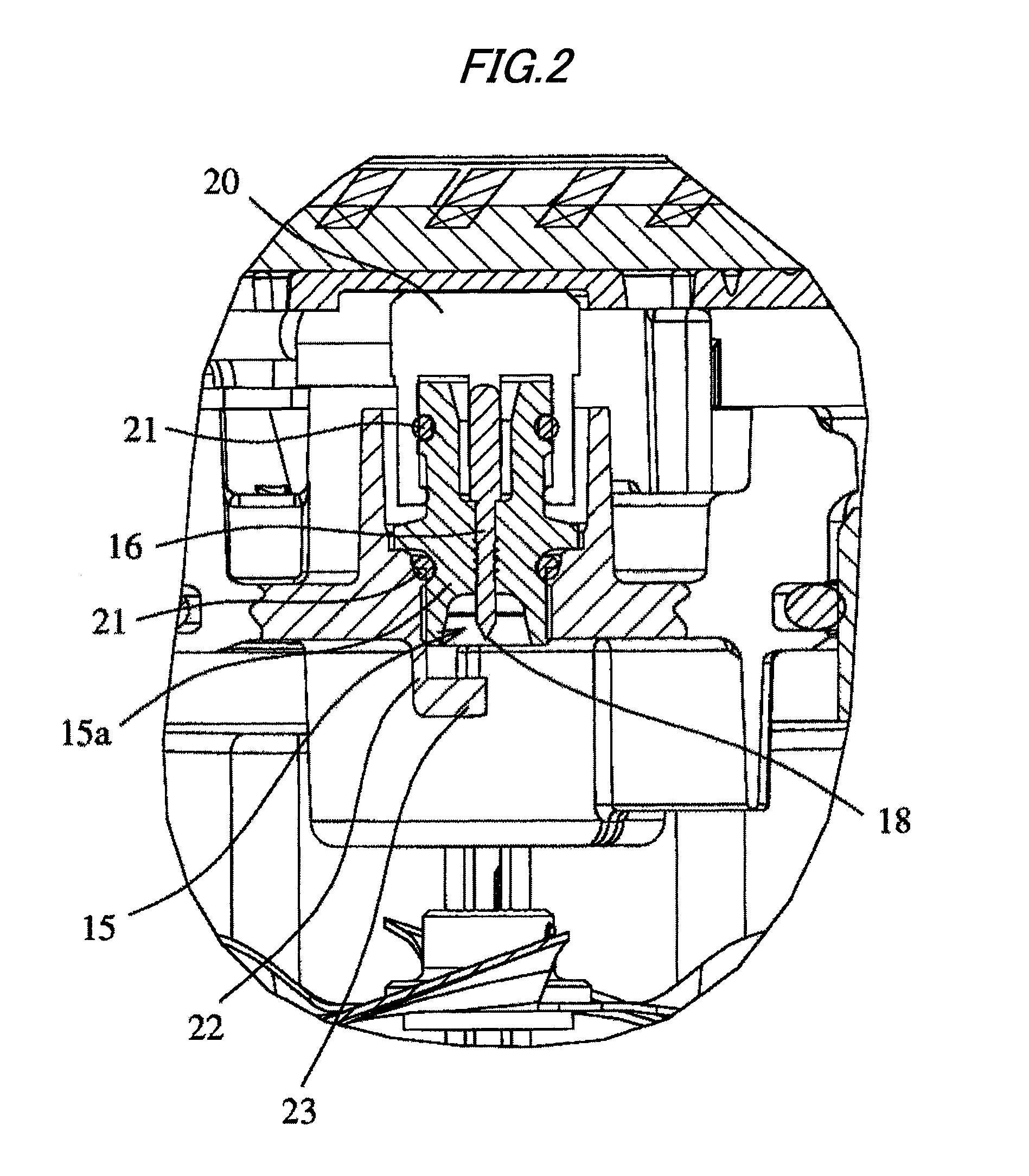
The invention provides a gas combustion type driving tool with an improved ignition plug design that reduces the accumulation of residue on the center electrode, thereby reducing maintenance work on the ignition plug. The tool includes a driving piston, a movable sleeve, and a cylinder head for opening and closing a combustion chamber. Mixture gas obtained by stirring and mixing combustible gas and air together in a combustion chamber by a fan is ignited by the ignition plug and combusted to drive the driving piston and nails. A stagnation part is provided between the exposed base portion of the center electrode of the ignition plug and the leading end of the center electrode to stagnate residue produced by the combustion of the mixture gas and delay its arrival at the leading end of the center electrode, thereby extending the life of the ignition plug and reducing the number of maintenance checks. The stagnation part can be formed by an annular step part, an annular protrusion, or a ring fitted and fixed to the center electrode.

Problems solved by technology

The combustion residue adhering to the center electrode of the ignition plug accumulates gradually on the leading end of the center electrode, which becomes a large cause to invite poor ignition of the ignition plug.
In particular, an attachment position of the ignition plug in the combustion chamber is a position at which the wind of a stirring fan is difficult to arrive.
In result, the poor ignition is caused.
However, the countermeasure for protecting the electrode in the above Patent Document 1 is taken for protection of the electrode from the oil or dust accumulated in the recess portion or the pocket portion, and there is particularly no electrode protecting countermeasure from a view of preventing a residue from adhering to the protruded electrode leading end portion.
By such the known electrode protecting countermeasure, it is not possible at all to solve the occurrence of trouble such as poor ignition due to adhesion of the residue to the ignition plug in the gas combustion type driving tool under the above circumstances.

Method used


Image

  • Gas combustion type driving tool
  • Gas combustion type driving tool
  • Gas combustion type driving tool

Examples


Embodiment Construction

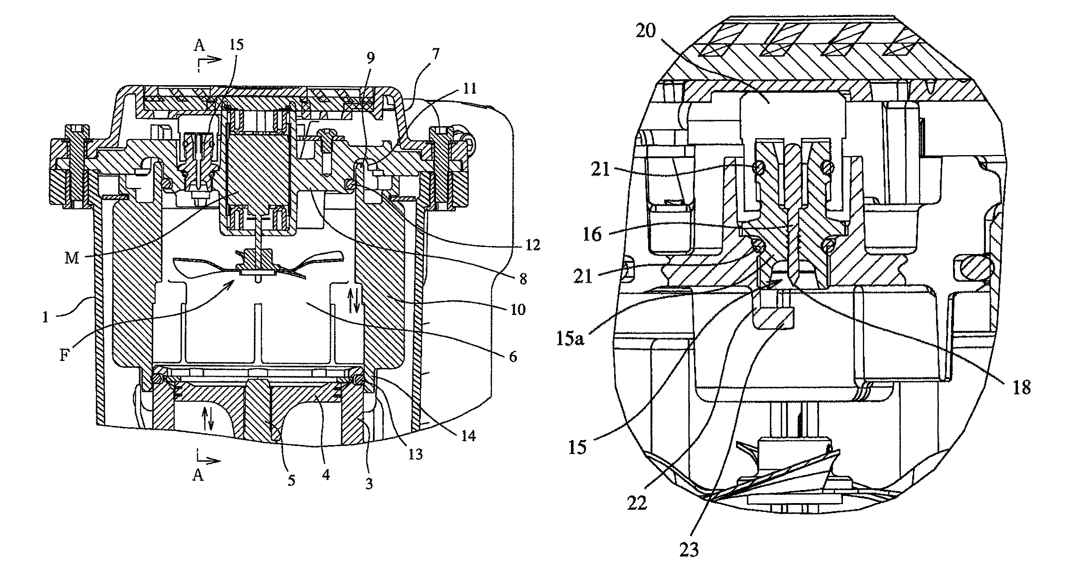
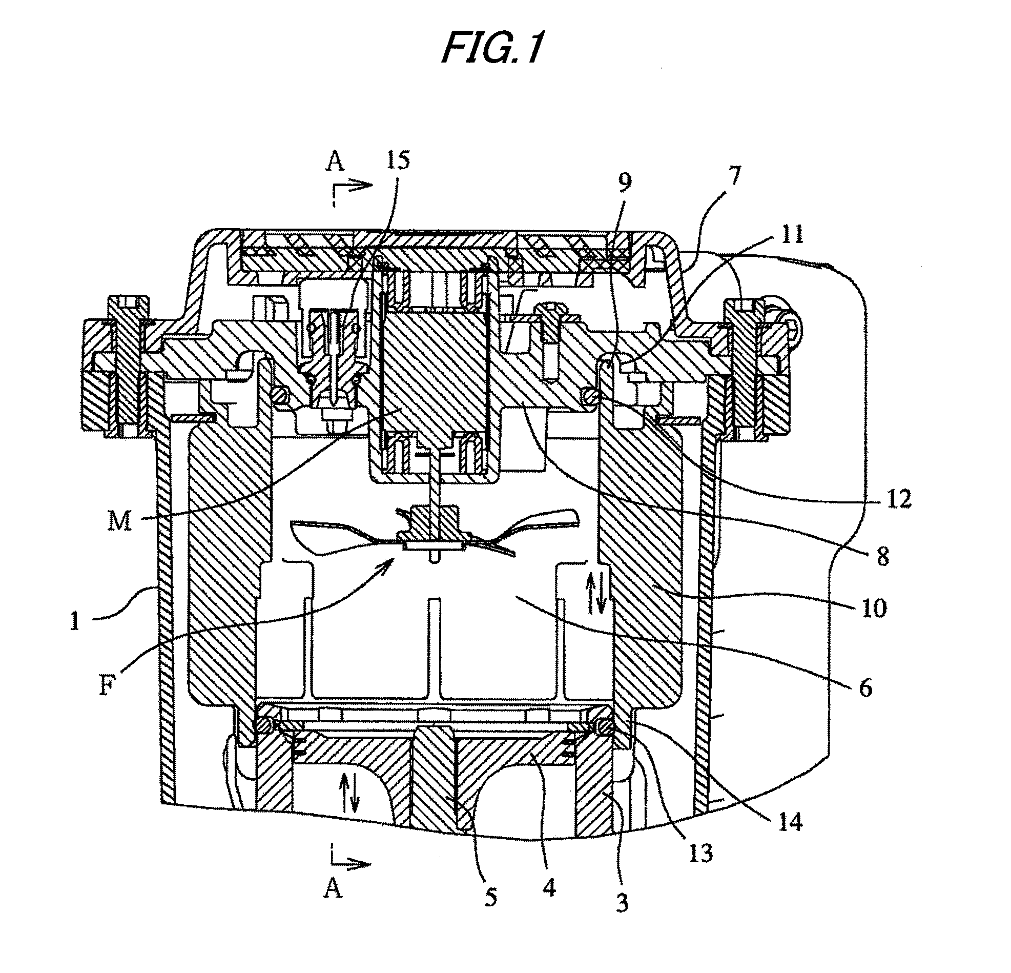
[0032]In FIGS. 1 and 2, reference numeral 1 denotes a tool body of a nailer as an example of a gas combustion type driving tool. At this tool body 1, a grip, which is not shown, is consecutively installed similarly to in the usual gas combustion type nailer. Below the tool body 1, a nose part for driving a nail and a magazine for supplying the nail into the nose are provided. Further, inside the tool body 1, a driving piston / cylinder mechanism is provided.

[0033]In the driving piston / cylinder mechanism, a driving piston 4 is slidably accommodated in a driving cylinder 3, and a driver 5 is integrally coupled to the lower portion of the driving piston 4.

[0034]Next, over the driving cylinder 3, a combustion chamber 6 is constituted in an openable and closable way. The combustion chamber 6 is formed by an upper end surface of the driving piston 4, and a movable sleeve 10 arranged between a the driving cylinder 3 and a cylinder head 8 formed inside an upper housing 7 movably up and down....


PUM


Abstract

A driving piston 4 is provided slidably up and down in a driving cylinder 3 arranged in a tool body 1. By moving a movable sleeve 10 provided at the upper portion of the driving cylinder 3 up and down, the movable sleeve 10 is brought into contact with and separated from the driving cylinder 3 and a cylinder head 8 provided above the driving cylinder 3, whereby a combustion chamber can be opened and closed. Mixture gas obtained by stirring and mixing combustible gas and air together in the combustion chamber by a fan 16 is ignited by an ignition plug 15 disposed at the cylinder head 8 and explosively combusted. By this high-pressure combustion gas, the driving piston 4 is impulsively driven, and a driver 5 coupled to the lower surface side of the driving piston drives nails. Between an exposed base portion of a center electrode of the ignition plug 15 which is exposed to the outside facedown and a leading end of the center electrode, there is provided a stagnation part 25 which stagnates temporarily a residue remaining after the combustion of the mixture gas.

Description

TECHNICAL FIELD[0001]The present invention relates to a gas combustion type driving tool in which power is supplied by combustion thereby to drive fasteners such as nails or the like, and particularly to a gas combustion type driving tool which is improved so that stain of a leading end of a center electrode of an ignition plug with a residue of combustion gas is delayed.BACKGROUND ART[0002]In a gas combustion type driving tool, as indicated in Patent Document 1, mixture gas obtained by stirring and mixing combustible gas and air together in a combustion chamber by a fan is ignited by sparks from an ignition plug and explosively combusted, and a driving piston is driven by gas pressure of this combustion gas to drive fasteners such as nails, screws, or the like. In such the gas combustion type driving tool, a combustion residue from additives of the combustion gas supplied in the combustion chamber can adhere to a center electrode of the ignition plug. The combustion residue adherin...

Claims


Application Information

Patent Timeline
Patent Type & Authority Patents(United States)
IPC IPC(8): B25C1/08H01T13/54
CPCB25C1/08B25C1/14F02P13/00F23Q3/00
Inventor UCHIYAMA, TORUMURAYAMA, KEIJIRO
Owner MAX CO LTD
Learn More