
One-finger gripper device

a one-finger, gripper technology, applied in the direction of metal-working holders, supporters, positioning apparatuses, etc., can solve the problems of significant size, unsuitable devices configured in this way, and problems affecting collocation, so as to facilitate and reduce the cost of making, the effect of less cumbersome and convenient collocation

Active Publication Date: 2011-08-30
GIMATIC SRL
View PDF8 Cites 0 Cited by
  • Summary
  • Abstract
  • Description
  • Claims
  • Application Information

AI Technical Summary

Benefits of technology

[0005]The objective of this invention is to avoid the drawbacks and problems of the known techniques with a one finger gripper easier and less expensive to make, and above all less cumbersome and consequently easier to collocate to be used.

Problems solved by technology

In this way, however, the pneumatic actuator dimensions accumulate which, often makes the device configured in this way unsuitable where the spaces available are restricted and / or not easily accessible as for example, with dies used with press-forging machines.
Also in this case, however, the gripper device has a significant size and can cause problems as regards to collocation.

Method used


Image

  • One-finger gripper device
  • One-finger gripper device
  • One-finger gripper device

Examples


Embodiment Construction

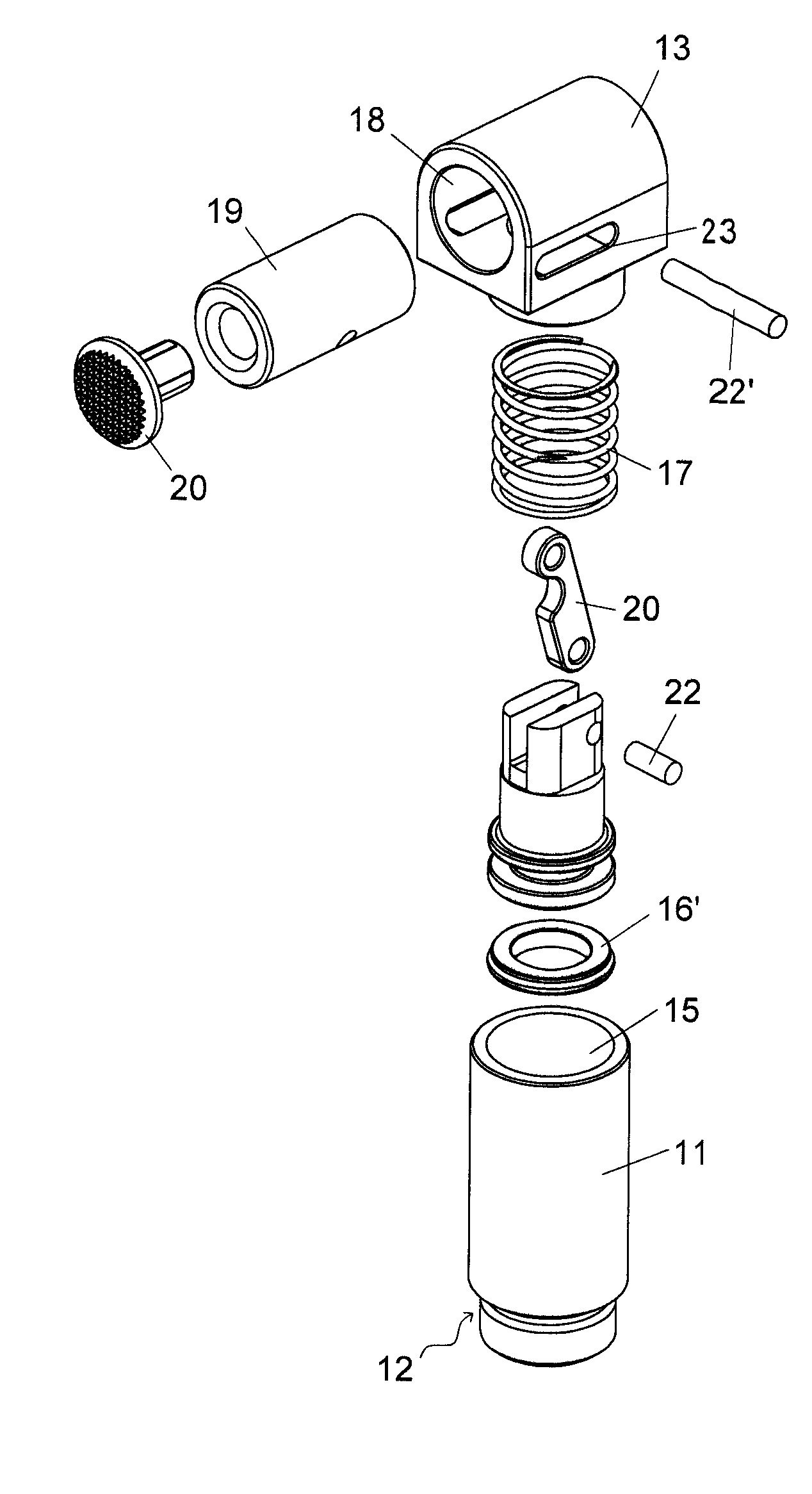
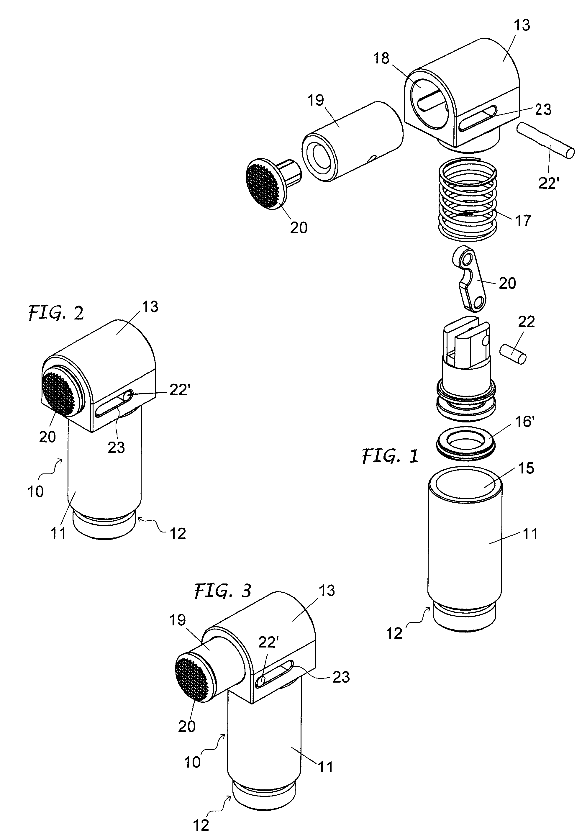
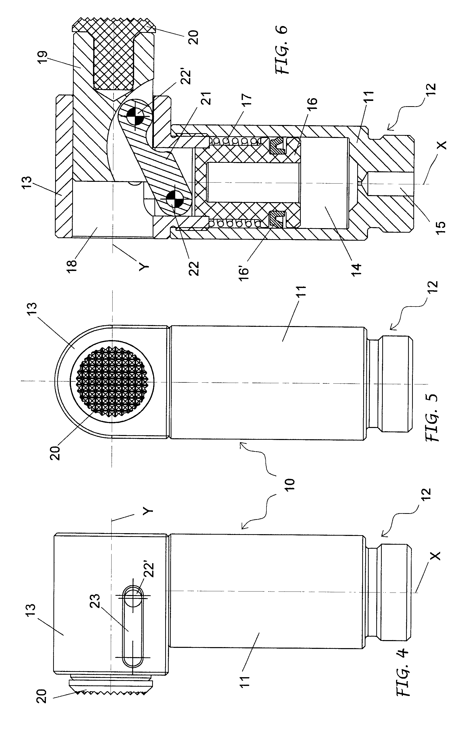
[0012]As shown, the tool proposed comprises a pneumatic actuator 10 comprising a body 11 with a base section 12 and integrated, on the opposite side, by a head element 13, screwed into it or however fixed to it.

[0013]The body 10 is preferably cylindrical and forms a chamber 14 open towards the head element 13 and in communication with a bottom hole 15 to which a feed conduit of a fluid under pressure, typically air, is connected. Said chamber 14 extends according to an X axis, and a piston 16 is housed in it with a relative seal 16′, which can be single or double acting.

[0014]In the example illustrated, the piston 16 is single acting and movable in one direction by means of the fluid under pressure fed through said bottom hole 15 and in the opposite direction by means of a return spring 17 placed between the piston 16 and the head element 13.

[0015]This head element 13 is provided with a seat 18 on a Y axis at a right angle to the X axis of the chamber 14 with a piston. The seat 18 h...


PUM


Abstract

The invention concerns a one-finger gripper device that comprises a pneumatic actuator (10) with a control piston (16) that is connected to a gripper jaw (19) for the movement of the latter between an active and idle position, and where the gripper jaw (19) is set up and susceptible to linear movements on a (Y) axis at right angles to the (X) axis of the control piston, the piston and the gripper jaw being connected to each other by a transmission at 90°.

Description

FIELD OF THE INVENTION[0001]This invention concerns a one-finger gripper tool usable in combination with at least another similar tool to grip, position and / or block bodies or items being handled, extracted from dies or the like.STATE OF THE TECHNIQUE[0002]The one finger gripper tools known from the technique basically comprise a pneumatic actuator with a piston which connects directly or indirectly up to a gripper jaw for the moving of the latter between an active and idle positions.[0003]According to a well known form of construction, the gripper jaw is positioned and is movable in axis with the piston it is connected to. In this way, however, the pneumatic actuator dimensions accumulate which, often makes the device configured in this way unsuitable where the spaces available are restricted and / or not easily accessible as for example, with dies used with press-forging machines.[0004]According to another way of construction, the gripper jaw is connected to the control piston, pivo...

Claims


Application Information

Patent Timeline
Patent Type & Authority Patents(United States)
IPC IPC(8): B25J15/00
CPCB25B5/122B25J15/0273
Inventor MAFFEIS, GIUSEPPE
Owner GIMATIC SRL
Learn More