No-Feed-Roll Corrugated Board or Paperboard Sheet Feeder Retrofit Apparatus and Method

a feeder and no-feed roll technology, applied in the field of no-feed-roll corrugated board or paperboard sheet feeder retrofit apparatus and method, can solve the problems of affecting the quality of the printed material, requiring expensive down-time for feed roll replacement, and becoming an excessively costly and time-consuming process, so as to achieve the effect of easy and less expensive retrofi

Pending Publication Date: 2022-03-03
SUN AUTOMATION
View PDF0 Cites 0 Cited by
  • Summary
  • Abstract
  • Description
  • Claims
  • Application Information

AI Technical Summary

Benefits of technology

[0009]Accordingly, it is a primary object of the present invention to overcome the above mentioned difficulties by providing a corrugated board or paperboard sheet feeder apparatus and retrofitting method which provides a sheet feeding feed system that is easier and less expensive to retrofit into a pre-existing, installed operating corrugated sheet or corrugated board processing machine such as a box making machine.
[0010]Briefly, the No-Feed-Roll corrugated board or paperboard sheet feeder apparatus and retrofitting method of the present invention provides a corrugated board or paperboard sheet feeder apparatus and retrofitting method that is easier and less expensive when retrofit into a pre-existing, installed operating corrugated sheet or corrugated board processing machine such as the box making machine 10 illustrated in FIG. 1A.
[0014]The primary servo motor in the initial variable velocity zone performs a specific motion profile designed to reduce the peak torque requirements of the machine. The peak torque specification is one of the leading limitations of commercially available servo motors. At the same time, traditional feeders need a significant amount of power to accelerate a sheet to machine velocity over a relatively short distance. To reduce required peak torque, the velocity profile for the sheet feeder of the present invention is designed to accelerate the sheet at a lower rate than what would normally be required over a specific distance. The primary servo motor in the initial velocity zone makes up for this by accelerating the sheet above machine speed momentarily so that the sheet will “catch up.” The primary servo motor in the initial velocity zone then decelerates the board to the selected machine velocity. The primary servo motor in the initial velocity zone performing such a motion profile requires a higher maximum velocity, but a lower peak torque rating than would otherwise be needed. By returning the board to the selected machine velocity at the proper time, it is ensured that the longest sheet that can be fed (maximum sheet) capability is not diminished. The sheet feeder configuration and retrofit method of the present invention insures that the retrofitted board or paperboard host machine, with the retrofitted feeder of the present invention, can accept and process the largest possible maximum feedable sheet size (e.g., 100% of the host machine's size), which will usually be increased over the pre-retrofit maximum feedable sheet size (which is typically usually 92% of the host machine's size).

Problems solved by technology

This results in some crushing of the paperboard which can weaken it and negatively affect print quality.
Feed roll replacement requires expensive down-time and can become an excessively costly and time-consuming process.
Such upgrades involve installation work which can last days and require extensive modifications to the pre-existing or installed corrugated board or paperboard sheet processing machine and the new sheet feeder.
The resulting system typically continues to rely on the use of feed rolls, and these requirements add expense and uncertainty to the process of retrofitting an installed, operating corrugated board processing machine such as a box making machine with a new or updated sheet feeder.
Sheet feeders with nip rolls or feed rolls (e.g., 3U and 3L) require adjustment to maintain the correct gap size in the nip for each type of sheet or board and if the gap is misadjusted, the feed rolls can damage or crush the sheets.
If a sheet feeder 10P of the type illustrated in FIG. 1C is retrofitted to an existing host machine (e.g., 10 or M), the result is a combination which is heavily dependent on the host machine's geometry and requires significant expensive modifications to (a) the host machine and (b) Prime's sheet feeder 10P during the retrofit installation process.
Such modifications add to the expense of the upgrade and the duration of downtime during which the machine is unavailable for its intended use.

Method used


Image

  • No-Feed-Roll Corrugated Board or Paperboard Sheet Feeder Retrofit Apparatus and Method
  • No-Feed-Roll Corrugated Board or Paperboard Sheet Feeder Retrofit Apparatus and Method
  • No-Feed-Roll Corrugated Board or Paperboard Sheet Feeder Retrofit Apparatus and Method

Examples


Embodiment Construction

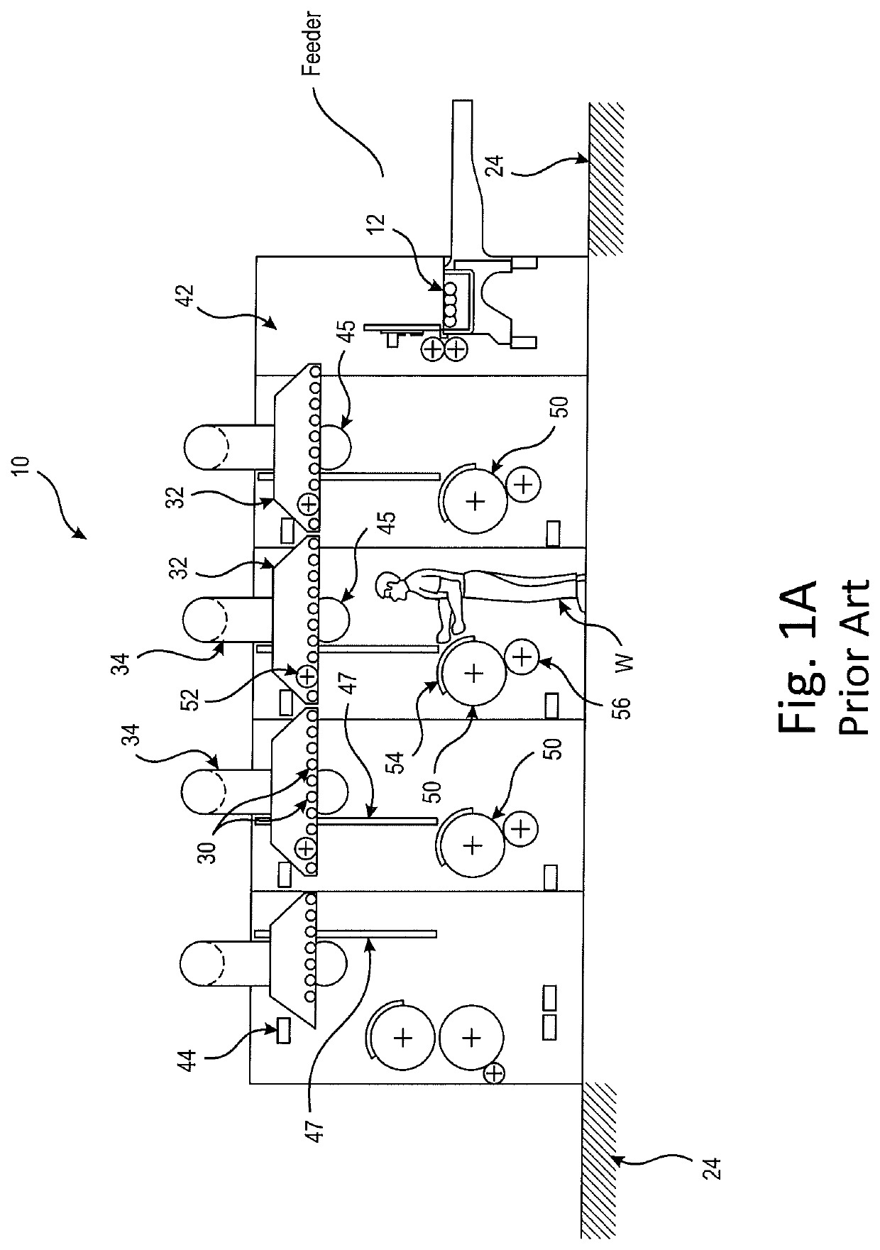
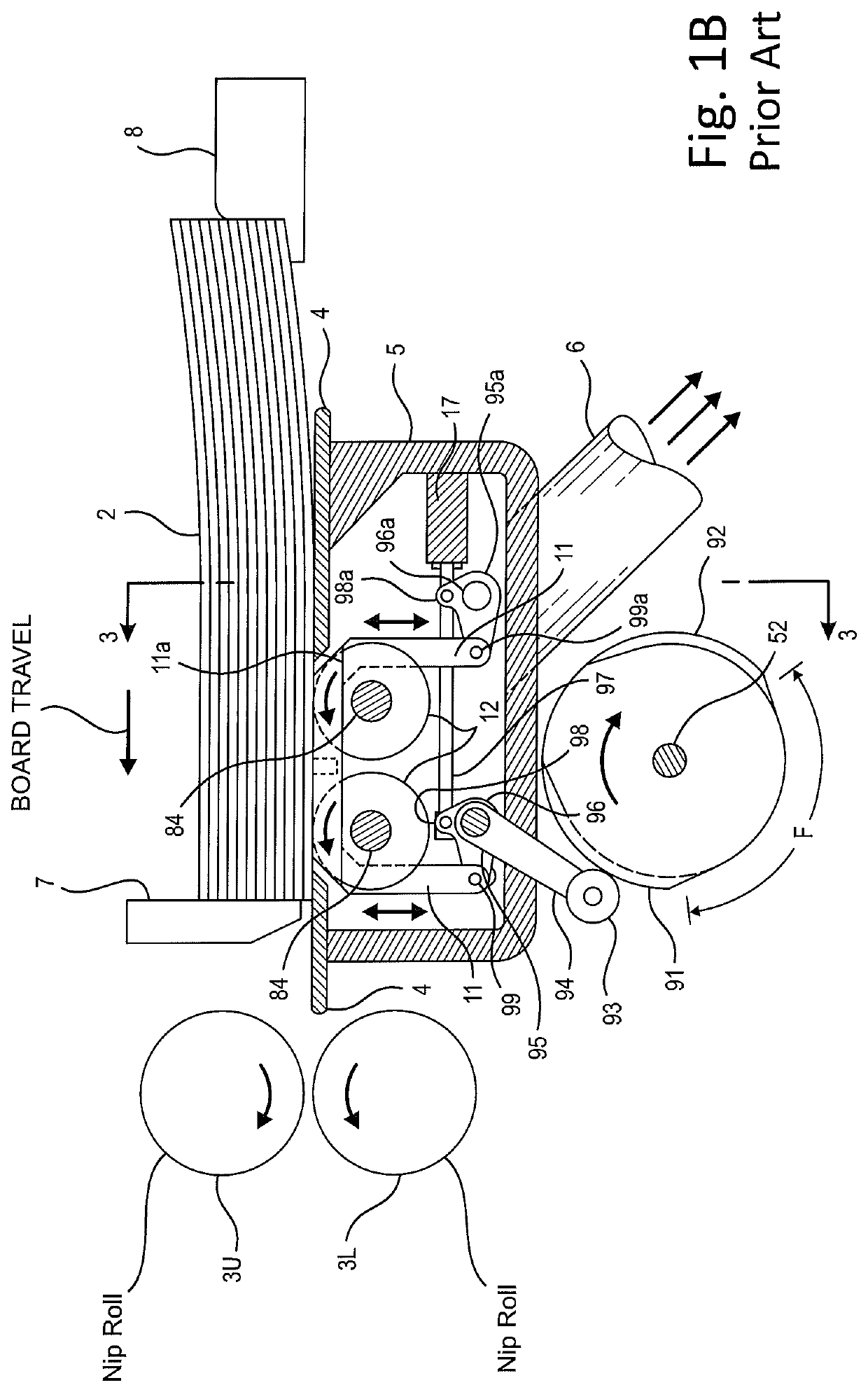
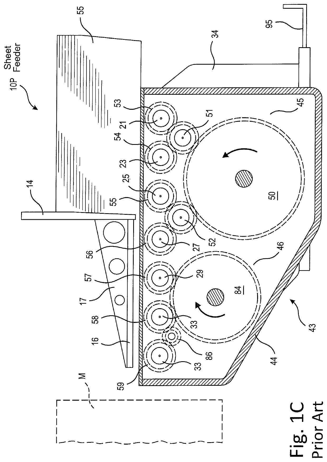
[0034]Turning now to a more detailed description of the present invention, as illustrated in FIGS. 2-7, the sheet or board feeding system 200 and method of the present invention does not require a mechanical drive input from or mechanical coupling with the host machine (e.g., a finishing machine for folding or making boxes from corrugated boards or sheets 10 or M) and instead is an entirely self-contained unit 200 which is driven with one or more motors, using sensed velocity or speed data from the host machine (10 or M) only as a speed reference. Critical functions performed by a feed table of sheet feeding system 200 are parameterized such that they can be scaled to different machinery with a change in a program stored in and executed by controller 300 in sheet feeding system 200. The host machine (e.g., 10 or M) is preferably modified or configured to be attached to the system's feed table 210. In the event that one or more nip or feed rolls (e.g., 3U, 3L) is a necessary componen...


PUM


Abstract

A self-contained no-feed-roll computer controlled corrugated board or paperboard sheet feeder apparatus 200 is configured to upgrade an installed corrugated board processing machine (e.g., 10) and includes a feed table surface 210 for boards (e.g., 2) having drive wheels (222W, 224W, 226W) in an initial variable velocity zone 220 which drives the board in a first motion profile through a first vacuum zone, and a second velocity zone 230 which then drives the board in a second motion profile through a second vacuum zone Retrofittable sheet feeder 200 also includes a controller 300 configured to receive predetermined velocity signals from the host machine 10 and generate (i) a first initial variable velocity control signal for initial variable velocity zone 220 and (ii) a second velocity control signal for second velocity zone 230 in response.

Description

REFERENCE TO RELATED APPLICATIONS[0001]This application claims priority to (a) related and commonly owned U.S. provisional patent application No. 62 / 635,373, filed Feb. 26, 2018 and entitled “No-Feed-Roll Corrugated Board or Paperboard Sheet Feeder Retrofit Apparatus and Method” and (b) PCT patent application No. PCT / US19 / 19574, filed Feb. 25, 2019 also entitled “No-Feed-Roll Corrugated Board or Paperboard Sheet Feeder Retrofit Apparatus and Method”, the entire disclosures of which are hereby incorporated herein by reference. The corrugated board processing subject matter of this invention is also related to the following commonly owned U.S. Pat. Nos. 5,184,811, 6,824,130 and 9,539,785, the entire disclosures of which are also incorporated herein by reference.BACKGROUND OF THE INVENTIONField of the Invention[0002]The present invention relates to feeder machines for corrugated boards or sheets, and to a system and method for retrofitting a new sheet feeder to an installed, operating ...

Claims


Application Information

Patent Timeline
Patent Type & Authority Applications(United States)
IPC IPC(8): B65H3/06B65H3/12B65H5/02
CPCB65H3/063B65H3/126B65H2403/50B65H2403/481B65H2406/30B65H5/021B31B50/064B31B50/07B31B50/042B31B50/88B31B50/20B65H3/0669B65H3/0692B65H5/066B65H7/18B65H2404/15422B65H2406/3122B65H2513/20B65H2515/32B65H2601/525B65H2601/61B65H2701/1764B65H2513/10B65H2220/01B65H2220/02
Inventor SCHLOTHAUER, AARONGARIS, RYANPROPERT, CRAIGHARTLAUB, TERRY
Owner SUN AUTOMATION
Why Eureka
Try Eureka