Inkjet head

a technology of inkjet and head, applied in the direction of printing, inking apparatus, etc., can solve the problems of low rigidity of the area and channel wall unstuckness

Inactive Publication Date: 2011-08-30
CANON KK
View PDF2 Cites 0 Cited by
  • Summary
  • Abstract
  • Description
  • Claims
  • Application Information

AI Technical Summary

Benefits of technology

[0009]The present invention provides an inkjet head that discharges ink stably by adjusting the adherence between the orifice plate and the recording element substrate to prevent the orifice plate and the recording element substrate from becoming unstuck.
[0011]The present invention prevents the channel walls from becoming unstuck to achieve stable discharging. This realizes a smaller and longer recording element and a denser and longer inkjet head, thereby satisfying a demand for a printer with a smaller size, a higher resolution, and a faster recording speed.

Problems solved by technology

When this area is too small, rigidity of the area may be low and channel walls may become unstuck.

Method used


Image

  • Inkjet head
  • Inkjet head
  • Inkjet head

Examples


first embodiment

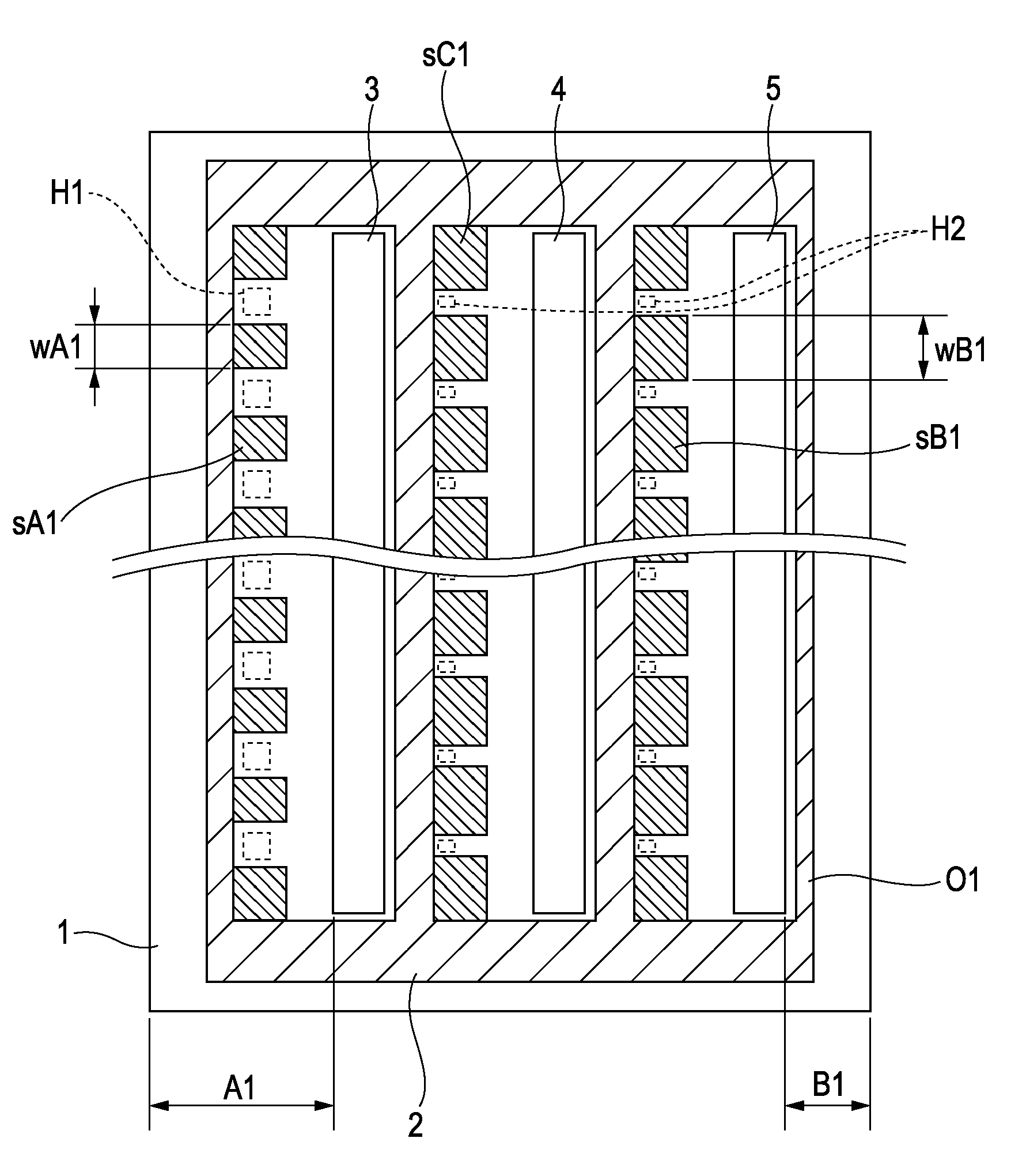
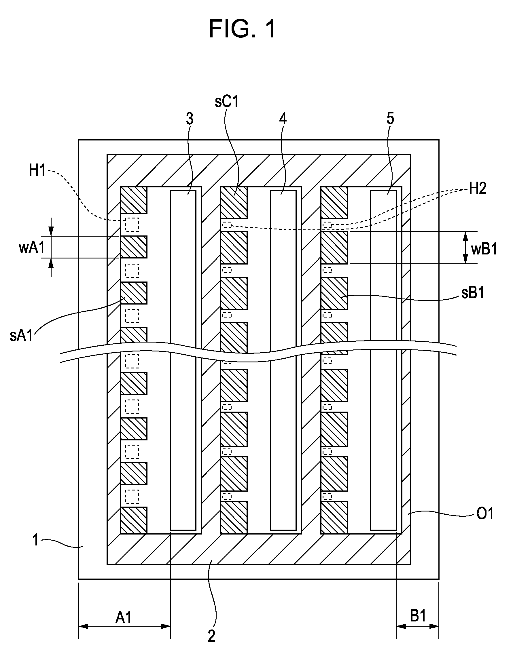
[0025]FIG. 1 shows a configuration according to the present invention. FIG. 1 shows a recording element substrate 1 on which an orifice plate 2 is stacked. In the embodiment, three supply ports 3, 4, and 5, corresponding to the three colors of ink, are formed on the recording element substrate 1 so as to extend through the substrate from the back to the front.

[0026]The recording element substrate 1 contacts the orifice plate 2 at ground areas (contact areas) sA1, sB1, sC1, and O1, which are shaded in the figure. At the ground areas sA1, sB1, and sC1, the recording element substrate 1 contacts parts of the orifice plate 2 serving as channel walls of ink channels. At the ground area O1, the recording element substrate 1 contacts parts of the orifice plate 2 excluding the parts serving as the channel walls. Energy generating elements H1, H2 discharge ink.

[0027]As shown in the figure, sets of a supply port and energy generating elements are arranged in the left-right direction of the re...

sixth embodiment

[0043]FIG. 6 shows a configuration according to the present invention. In this embodiment, the amount of ink discharged from each discharge port tA2 at the supply port 3 is 5 picoliters and the amount of ink discharged from each discharge port tB2 at the supply port 5 is about 1 picoliter. Ink channels for discharge ports tD with a discharge amount of 10 picoliters are disposed in a staggered manner between the ink channels. To achieve excellent refillability, discharge ports with a larger discharge amount are disposed closer to the supply port. In this embodiment, the ink channels are disposed at the same pitch corresponding to 1200 dpi at each of the supply ports 3, 4, and 5.

[0044]In this embodiment, the ground area sA3 is smaller than the ground area sB3 (sA33), because a width wB3 of channel walls forming ink channels for discharge amounts of 1 and 10 picoliters is greater than a width wA3 of channel walls forming ink channels for discharge amounts of 5 and 10 picoliters (wA33)....


PUM


Abstract

An inkjet head includes a recording element substrate, on which sets of energy generating elements generating energy to discharge ink and a supply port supplying ink to discharge ports are arranged, and an orifice plate including the discharge ports. The sets include a set having a first supply port disposed at a first edge of the substrate and a set having a second supply port disposed at a second edge of the substrate opposite the first edge. The distance between the second edge and the second supply port is shorter than the distance between the first edge and the first supply port. A contact area between the substrate and second channel walls that form second ink channels communicating with the second supply port is larger than the contact area between the substrate and first channel walls that form first ink channels communicating with the first supply port.

Description

BACKGROUND OF THE INVENTION[0001]1. Field of the Invention[0002]The present invention relates to an inkjet head that performs recording by discharging ink to a recording surface of a recording medium. In particular, the present invention relates to an inkjet head including supply ports that extend through a recording element substrate and an orifice plate stacked on the recording element substrate.[0003]2. Description of the Related Art[0004]An inkjet recording apparatus, which uses a non-impact recording method, has advantages of making little noise during recording and performing high-speed and high-resolution recording on various recording media. Examples of the inkjet recording apparatus include the apparatus having such characteristics described in U.S. Pat. No. 6,863,381. The document discloses a configuration in which nozzle arrays for discharging ink are each disposed on one side of a corresponding supply port (ink via) on a recording element substrate (heater chip), and the...

Claims


Application Information

Patent Timeline
Patent Type & Authority Patents(United States)
IPC IPC(8): B41J2/05
CPCB41J2/1404B41J2002/14403B41J2002/14475B41J2202/11
Inventor KUDO, SATOSHIINADA, GENJI
Owner CANON KK
Why Eureka
Try Eureka