Impeller of centrifugal fan and centrifugal fan disposed with the impeller

a technology of centrifugal fans and impellers, which is applied in the direction of blade accessories, machines/engines, waterborne vessels, etc., can solve the problems of difficult drawbacks such as squeaking and wind roar, and achieve the effects of preventing deformation of hollow blades, reducing weight of impellers, and improving blowing performance and noise performan

Active Publication Date: 2011-08-30
DAIKIN IND LTD
View PDF40 Cites 45 Cited by
  • Summary
  • Abstract
  • Description
  • Claims
  • Application Information

AI Technical Summary

Benefits of technology

[0006]It is an object of the present invention to enable, in a centrifugal fan disposed with a resin-made impeller of the type that sucks in gas from a rotating shaft direction and blows out the gas in a direction intersecting the rotating shaft, a reduction in the weight of the impeller even when utilizing blades that extend while twisting in the shaft direction.

Problems solved by technology

Thus, it becomes difficult for drawbacks such as squeaking and wind roar to occur because the second surface portions attached to the first surface portions are prevented from rising due to centrifugal force and the hollow blades are prevented from being deformed.

Method used


Image

  • Impeller of centrifugal fan and centrifugal fan disposed with the impeller
  • Impeller of centrifugal fan and centrifugal fan disposed with the impeller
  • Impeller of centrifugal fan and centrifugal fan disposed with the impeller

Examples


modified examples 1 to 3

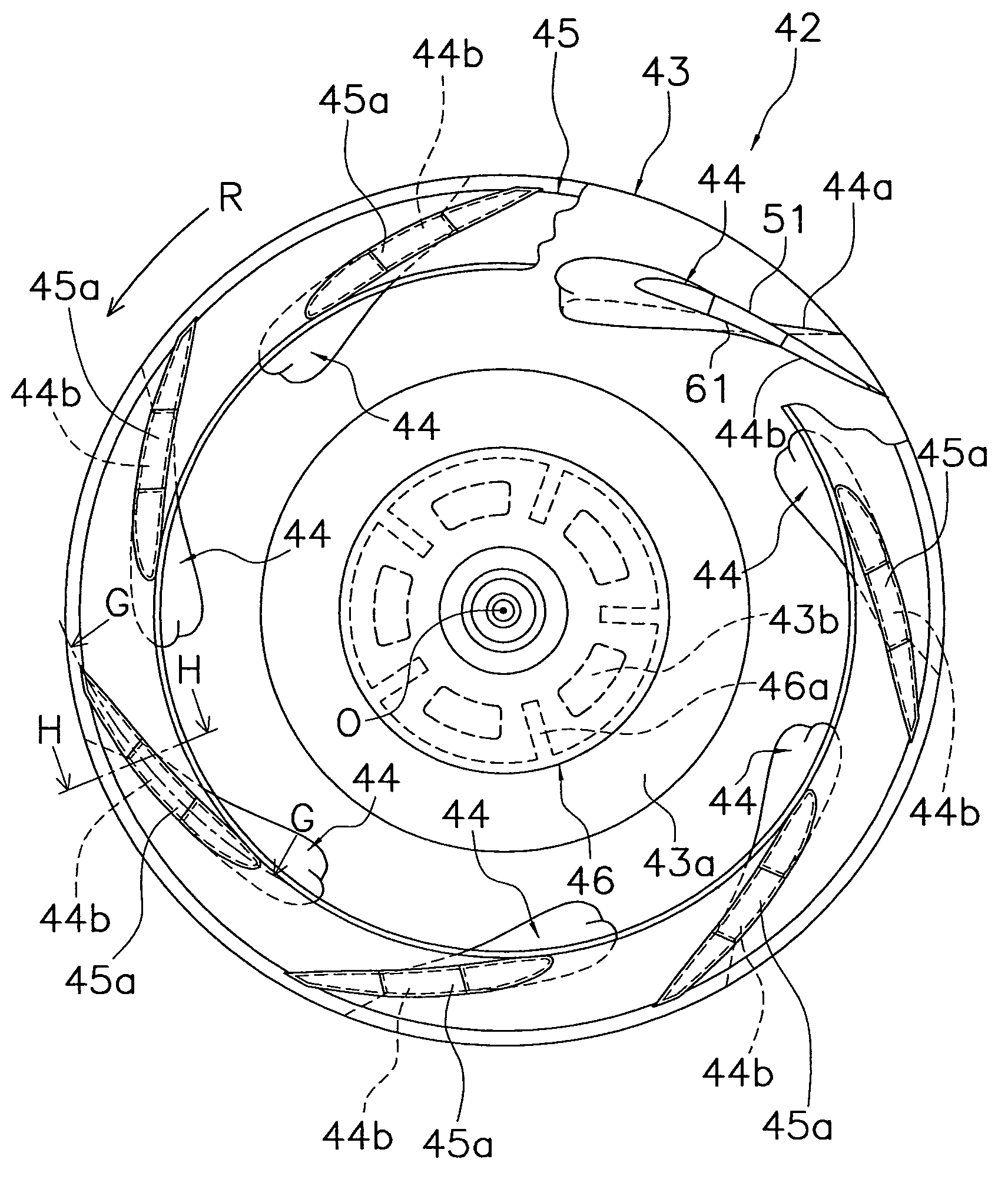
[0131]As shown in FIG. 7, each of the blades 44 in the preceding embodiment is divided such that the blade cover 61 configures the portion of the negative-pressure surface 44f excluding the rear edge portion serving as part of the blade 44 and such that the blade body 51 configures the positive-pressure surface 44e and the rear edge portion of the negative-pressure surface 44f. However, each of the blades 44 may also have the following divided structure between the blade cover 61 and the blade body 51 in order to promote the hollowing of the blade 44 and prevent drawbacks such as squeaking and wind roar.

[0132]For example, as shown in FIG. 15 (a view showing a blade according to Modified Example 1, corresponding to FIG. 7), the blade 44 may be divided such that the blade body 51 configures not only the rear edge portion of the negative-pressure surface 44f but also the front edge portion of the negative-pressure surface 44f, and such that the blade cover 61 configures the negative-pr...

modified example 4

[0136]In the preceding embodiments, hollowing was promoted by giving each of the blades 44 a divided structure between the blade body 51 and the blade cover 61, the blade body 51 was fixed to the end plate 43 and the end ring 45 molded separately from the blade body 51, and the blade cover 61 configuring at least part of the negative-pressure surface 44f of the blade 44 was attached to the blade body 51 by fitting it into the blade body 51, whereby the impeller 42 was configured where it is difficult for drawbacks such as squeaking and wind roar to occur.

[0137]However, the blade bodies 51 and the end plate 43 and the end ring 45 do not always have to be separate members in order to promote the hollowing of the blades 44 and prevent drawbacks such as squeaking and wind roar.

[0138]For example, the blade bodies 51 and the end plate 43 may be integrally molded and the end ring 45 may be molded as a separate member. By configuring the invention in this manner, the blade covers 61 are att...

modified example 5

[0141]In the preceding embodiments, because the blade cover 61 configuring the majority of the negative-pressure surface 44f of each of the blades 44 was a member separate from the blade body 51 and the end plate 43 and the end ring 45, there were few restrictions in direction in which it is removed from the mold when it is molded, and a concavo-convex shape could be easily formed in the surface of the blade cover 61. Also, when the blade body 51 is molded separately from the end plate 43 and the end ring 45, a concavo-convex shape can also be easily formed in the surface of the blade body 51.

[0142]For example, as shown in FIG. 18 (a view showing a blade according to Modified Example 5, corresponding to FIG. 5) and FIG. 19 (a view showing a blade according to Modified Example 5, corresponding to FIG. 5), plural dimples 51a and 61a can be formed in the surfaces of the blade body 51 and the blade cover 61.

[0143]By disposing the plural dimples 51a and 61a in the surfaces of the blade b...


PUM

PropertyMeasurementUnit
pressureaaaaaaaaaa
centrifugal forceaaaaaaaaaa
lengthaaaaaaaaaa

Abstract

An impeller of a centrifugal fan includes an end plate, a plurality of blades and an end ring. The blades include blade bodies that are annularly disposed around a shaft and fixed to the end plate. The blades further include blade covers that are attached to the blade bodies. The blade covers and the blade bodies form a hollow space. The end ring is disposed such that it sandwiches the plural blades between itself and the end plate in a shaft direction. The blade covers form at least part of negative-pressure surfaces.

Description

CROSS-REFERENCE TO RELATED APPLICATIONS[0001]This U.S. National stage application claims priority under 35 U.S.C. §119(a) to Japanese Patent Application No. 2003-396522, filed in Japan on Nov. 27, 2003 the entire contents of which are hereby incorporated by reference.TECHNICAL FIELD[0002]The present invention relates to an impeller of a centrifugal fan and to a centrifugal fan disposed with the impeller, and more particularly relates to an impeller of a centrifugal fan and to a centrifugal fan disposed with the impeller which sucks in gas from a rotating shaft direction and blows out the gas in a direction intersecting the rotating shaft.BACKGROUND ART[0003]Among ventilation systems, air conditioners and air cleaners, sometimes a centrifugal fan such as a turbofan or a diagonal-flow fan of the type that sucks in gas from a rotating shaft direction and blows out the gas in a direction intersecting the rotating shaft is used. The impeller configuring the centrifugal fan is mainly conf...

Claims


Application Information

Patent Timeline
Patent Type & Authority Patents(United States)
IPC IPC(8): F04D29/30F04D29/02F04D29/28
CPCF04D29/282F04D29/30B29C66/124B29C66/12469B29C65/16Y10T29/49339B29C66/5344B29C66/5346B29C66/543B29L2031/08Y10T29/49329B29C65/1635F04D29/02
Inventor SANAGI, TSUNEHISANISHINO, HISANORITERAKAWA, AZUMI
Owner DAIKIN IND LTD
Why Eureka
Try Eureka