Block for filtering particles contained in exhaust gases of an internal combustion engine

Inactive Publication Date: 2011-08-30
SAINT GOBAIN CENT DE RES & DEVS & DETUD EUROEN
View PDF20 Cites 2 Cited by
  • Summary
  • Abstract
  • Description
  • Claims
  • Application Information

AI Technical Summary

Benefits of technology

[0015]It is the object of the invention to provide a

Problems solved by technology

After a certain period of use, the particulates, or “soot”, accumulated in the inlet channels 14e of the filter body 3 impair the performance of the eng

Method used


Image

  • Block for filtering particles contained in exhaust gases of an internal combustion engine
  • Block for filtering particles contained in exhaust gases of an internal combustion engine
  • Block for filtering particles contained in exhaust gases of an internal combustion engine

Examples


Example

[0045]In these figures, which are nonlimiting, the various elements are not necessarily shown to the same scale. Identical references have been used in the various figures to denote identical or similar elements.

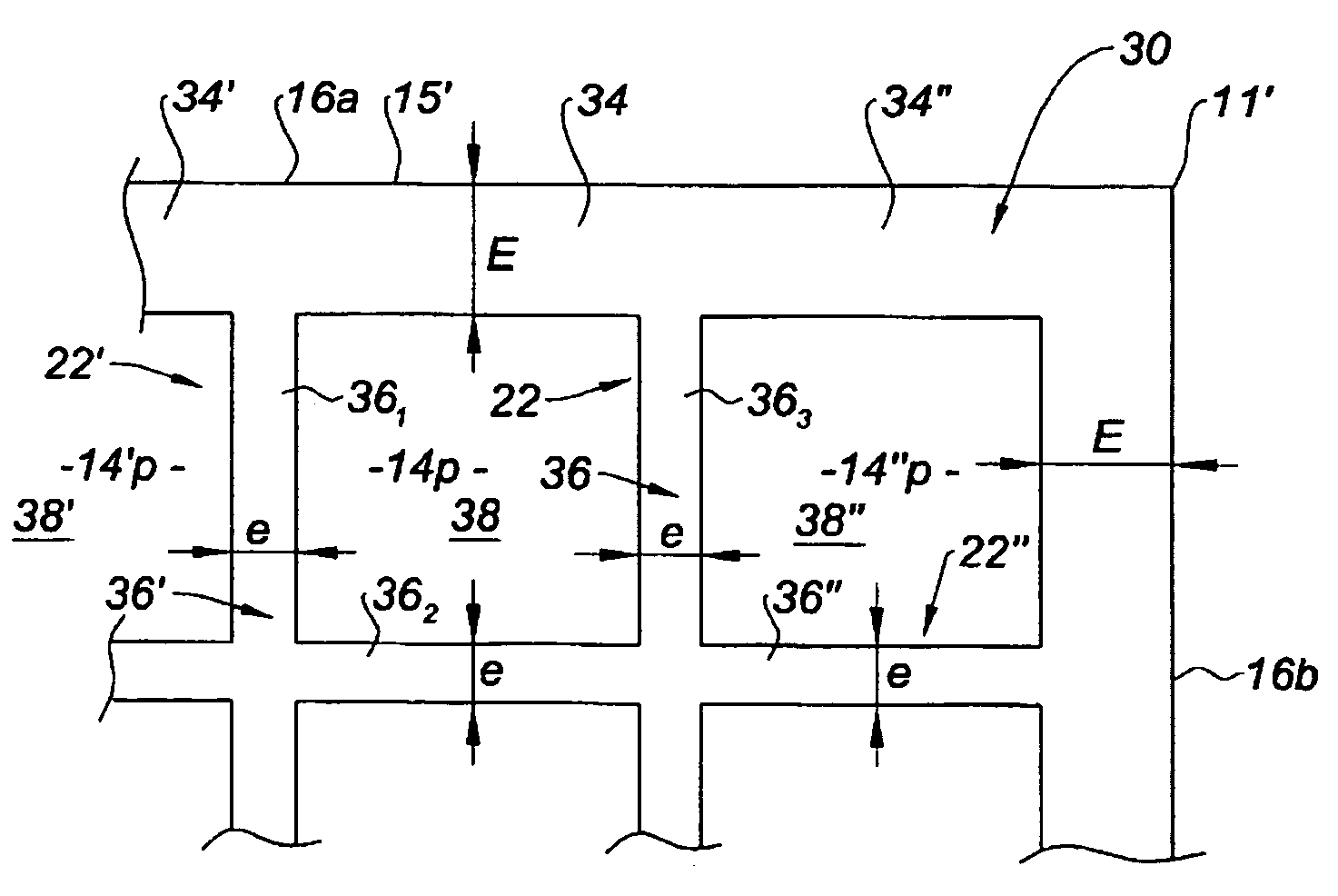
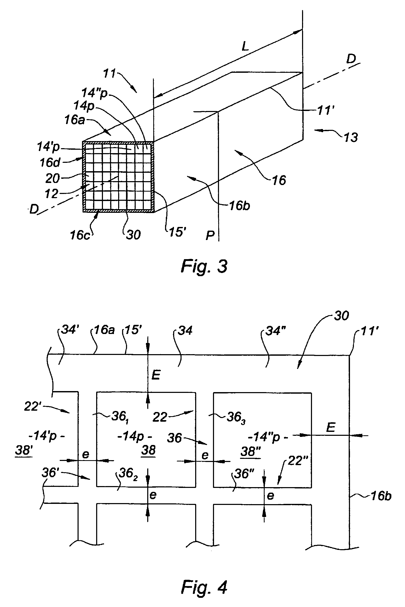
[0046]According to the invention, a portion of side wall of a channel comprises a “reinforcement” when it is thicker than the rest of the side wall of this channel. The channel is then dubbed a “reinforced channel”. As shown in FIG. 4, to measure a thickness of a wall of a channel, one takes a position opposite this wall, thereby excluding any thickness measurement in the corners of the internal volume of this channel.

[0047]The expression “reinforcing partition” is applied to a set of wall portions having a reinforcement, said set forming a continuous surface, plane or not.

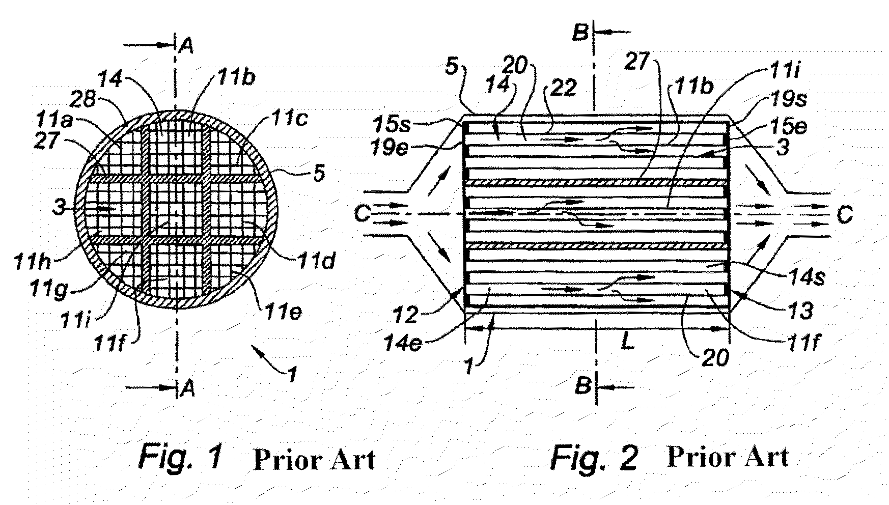
[0048]FIGS. 1 and 2 having been described in the preamble, we shall now refer to FIG. 3, also partially described above.

[0049]The filter block 11 shown in FIG. 3 comprises a reinforcing partition 30 that f...


PUM

PropertyMeasurementUnit
Timeaaaaaaaaaa
Flow rateaaaaaaaaaa
Structureaaaaaaaaaa

Abstract

A block, particularly for filtering particulates present in the exhaust gases of an internal combustion engine, includes a plurality of flow channels for the gases (14e,14s), each of the channels (14e,14s) being bounded by a side wall (22), a plug (15e,15s) and an opening (19e,19s) terminating outwardly. The block according to the invention is remarkable in that a first portion (34) of the side wall (22) of at least one of the channels (14p,14p″), called the “reinforced channel”, includes a reinforcement compared to the rest of the side wall (22) forming a second portion (36) of the side wall (22), the ratio (R) of the thickness of the first portion (34) to the thickness of the second portion (36), in any transverse plane of section (P), being between 1.1 and 3.

Description

FIELD OF THE INVENTION[0001]The invention relates to a block and to a body formed by assembling a plurality of said blocks, used in particular for filtering particulates present in the exhaust gases of an internal combustion engine, particularly of the diesel type.BACKGROUND OF THE INVENTION[0002]Conventionally, before being released to the open air, the exhaust gases may be purified by means of a particulate filter like the one shown in FIGS. 1 and 2, known in the prior art.[0003]A particulate filter 1 is shown in FIG. 1 in a transverse cross section, along the plane of section B-B shown in FIG. 2, and in FIG. 2 in a longitudinal cross section along the plane of section A-A shown in FIG. 1.[0004]The particulate filter 1 conventionally comprises at least one filter body 3, inserted in a metal housing 5. The filter body 3 results from the assembly and machining of a plurality of blocks 11, referenced 11a-11i. [0005]To fabricate a block 11, a ceramic material (cordierite, silicon carb...

Claims


Application Information

Patent Timeline
IPC IPC(8): B01D24/00B01D39/20B01D46/24F01N3/022F01N3/28F01N13/04
CPCB01D46/2474F01N3/0222F01N13/017B01D46/2466B01D2046/2496F01N2260/18F01N2330/06Y10T428/24149F01N2330/30F01N2450/28Y02T10/20Y10S55/30F01N2330/14Y02T10/12B01D46/2498B01D46/2478B01D46/2476B01D46/2482B01D46/2462
Inventor BARDON, SEBASTIENBRIOT, ANTHONYGLEIZE, VINCENT
Owner SAINT GOBAIN CENT DE RES & DEVS & DETUD EUROEN
Why Eureka
Try Eureka