Card level enclosure system having enhanced thermal transfer and improved EMI characteristics

a card level and enclosure technology, applied in the direction of printed circuit board receptacles, electrical apparatus casings/cabinets/drawers, cooling/ventilation/heating modifications, etc., can solve the problem that the general motherboard/expansion card architecture is not well suited for mobile applications, and achieve the effect of effective conductive and convective thermal coupling and efficient removal of hea

Active Publication Date: 2011-08-30
AUSTRALIAN RAIL TRACK CORP
View PDF4 Cites 13 Cited by
  • Summary
  • Abstract
  • Description
  • Claims
  • Application Information

AI Technical Summary

Benefits of technology

The present invention provides an encasement for each expansion card or daughterboard in a protective enclosure that provides a measure of physical protection and EMI shielding of the expansion card while providing effective conductive and convective thermal coupling between the expansion card and the ambient environment to efficiently remove heat therefrom.
In a preferred embodiment, first and second sub-enclosures interengage to form an enclosure assembly that substantially surrounds the major surface areas of the expansion card while providing support along at least some of the edges thereof. Additional components then substantially fully enclose the expansion card to provide a protected volume that provides both physical protection and EMI shielding for the electronic and electrical components on the expansion card while providing enhanced heat transfer therefrom.
The embodiments provide two primary thermal paths from the electronic components via direct conductive heat transfer from at least some of the edges of the expansion cards and convective heat transfer from the electrical components to the enclosure itself. If desired, various of the integrated circuits can also be directly thermally coupled to their enclosure by using a thermally conductive interface material or a thermally conductive gap filler. The convective thermal paths and the various thermal conductive paths keep the temperature differential between the electronic components and the enclosure to a minimum to ensure efficient heat transfer.

Problems solved by technology

While these board-retaining arrangements are adequate for stationary applications with a minimum of vibration, the generic motherboard / expansion card architecture is not well suited for mobile applications where the system will be exposed to vibrations, shock forces, jolts, and other accelerations or G-forces.

Method used


Image

  • Card level enclosure system having enhanced thermal transfer and improved EMI characteristics
  • Card level enclosure system having enhanced thermal transfer and improved EMI characteristics
  • Card level enclosure system having enhanced thermal transfer and improved EMI characteristics

Examples


Embodiment Construction

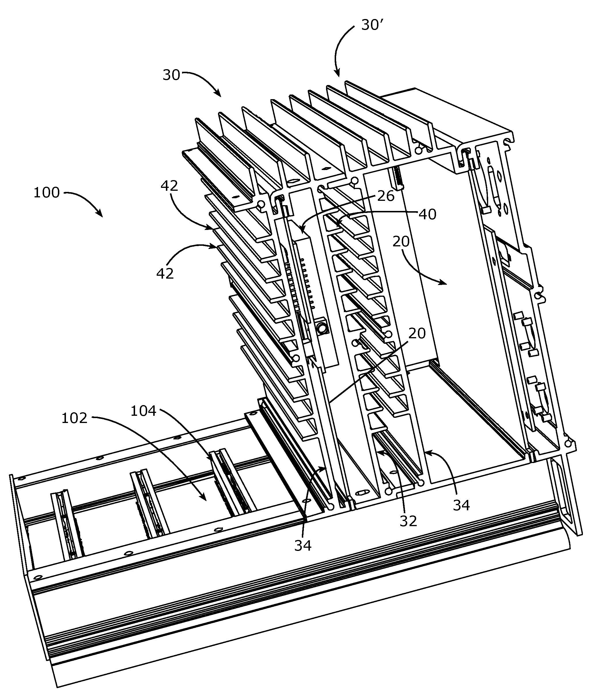
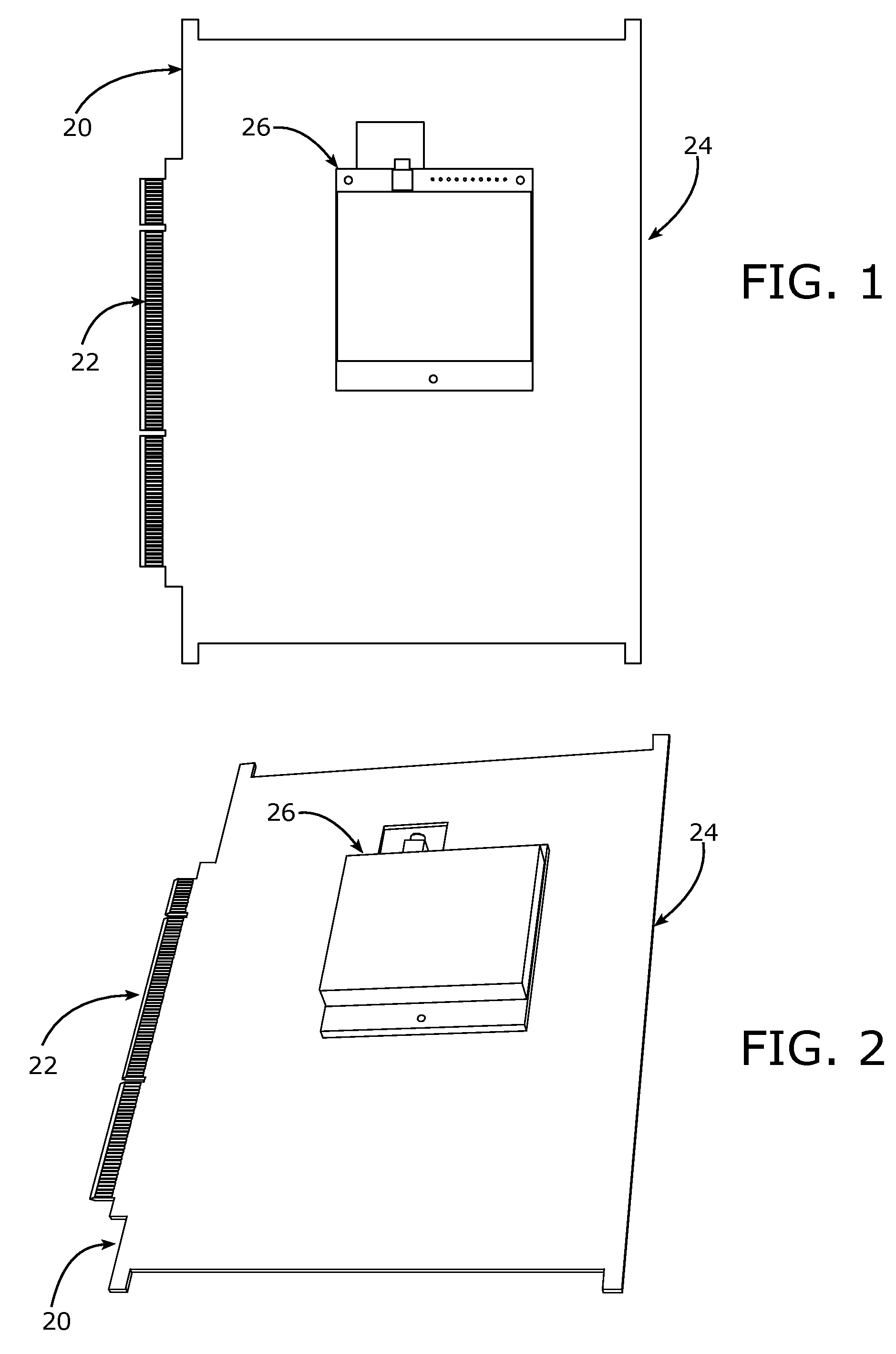
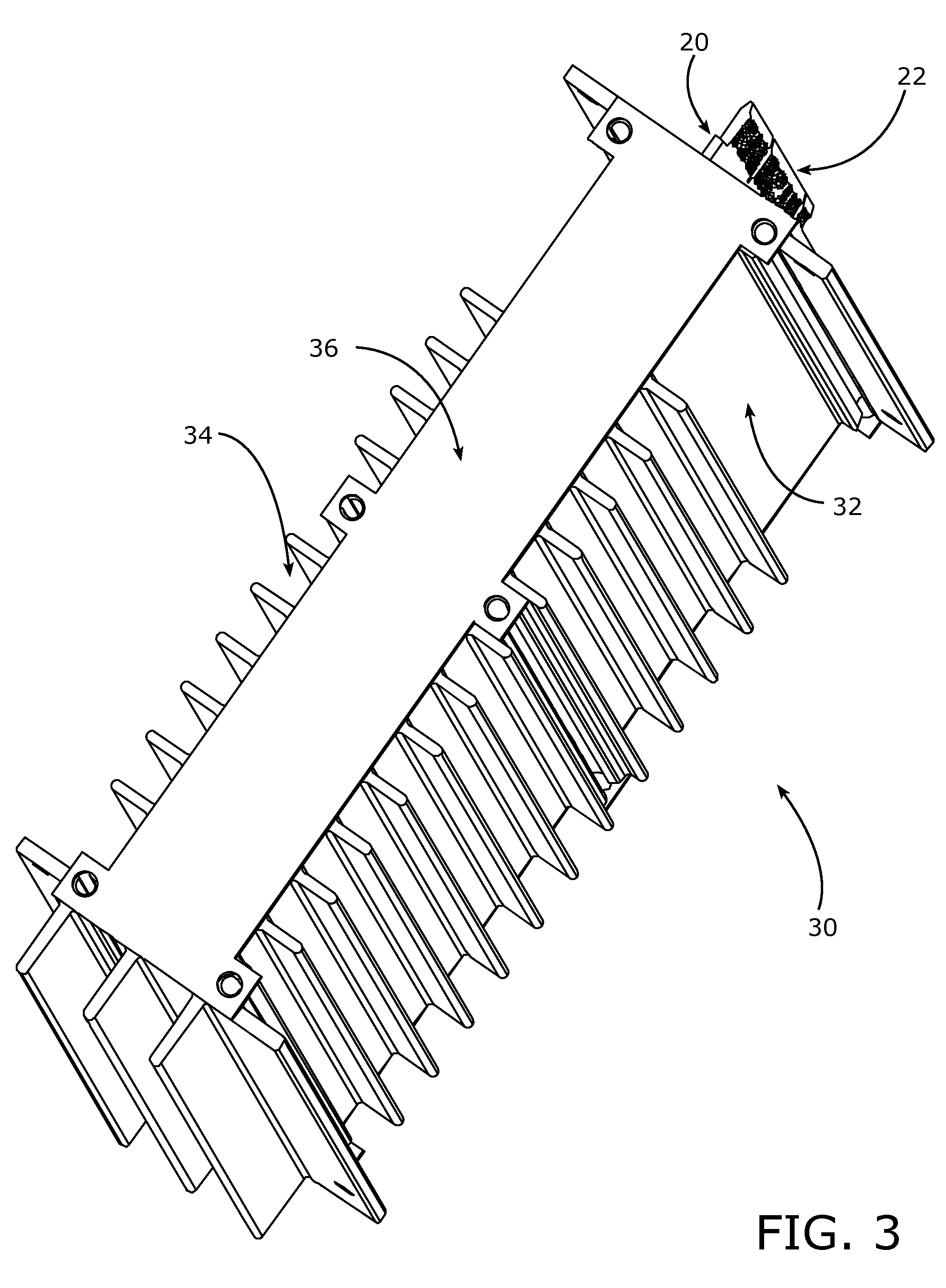
FIG. 1 is a plan view and FIG. 2 is an isometric view of a representative or example expansion card 20 having an edge connector 22 on a forward or connector-side of the expansion card 20 and defined by a plurality of spaced parallel conductive traces (unnumbered) and a rear edge 24 on the side opposite the front or connector side. The expansion card 20 shown is representative of a contemporary PCI architecture; however, the invention is suitable for use with any type of known interface board including the ISA, AT, EISA, AGP, and current and proposed PCI variants as well as any other board configurations that may or may not correspond to an industry-accepted standard. As shown, the board is populated with electronic components as symbolically represented at 26, and, while not shown, can include one or more subsidiary boards, currently known a “mezzanine” boards. For those components that require augmented heat removal, a heat sink and / or fan can be mounted upon or associated with the...


PUM


Abstract

An enclosure or containment system for expansion cards includes first and second sub-enclosures that interengage to form an enclosure assembly that substantially surrounds the major surface areas of the expansion card while providing support along some of the edges thereof to provide a protected volume that physically protects and shields the electronic and electrical components on the expansion card while providing enhanced heat transfer therefrom.

Description

BACKGROUND OF THE INVENTIONThe present invention relates to printed circuit board systems of the type having a mainboard (also known as a motherboard) into which one or more printed circuit boards (known as expansion cards or daughterboards) are connected via connector arrangements and, more particularly, to an enclosure system for the expansion cards that provides a ruggedized containment for each expansion card and which maximizes the opportunity for heat transfer from the expansion card to the external environment and which also provides improved EMI shielding.In the packaging of electronic systems using a plurality of printed circuit boards, one common architecture involves a primary printed circuit board, variously referred to as a backplane, a baseboard, a mainboard, or, more commonly, as a motherboard, that includes a plurality of connectors for receiving subsidiary printed circuit boards, commonly referred as expansion cards or daughterboards. With this type of system, curre...

Claims


Application Information

Patent Timeline
Patent Type & Authority Patents(United States)
IPC IPC(8): H05K5/00H05K7/14H05K7/18
CPCH05K7/1429H05K9/0062H05K7/20545
Inventor METZGER, THOMAS R.
Owner AUSTRALIAN RAIL TRACK CORP
Why Eureka
Try Eureka