
Techniques for obtaining a specified lifetime for a data storage device

a data storage and lifetime technology, applied in the field of data storage, can solve the problems of different storage technologies, such as flash memory devices, primarily failing, wearout, etc., and achieve the effect of reducing the current performance rate, and reducing the current rate of usag

Active Publication Date: 2011-08-30
EMC IP HLDG CO LLC
View PDF16 Cites 160 Cited by
  • Summary
  • Abstract
  • Description
  • Claims
  • Application Information

AI Technical Summary

Benefits of technology

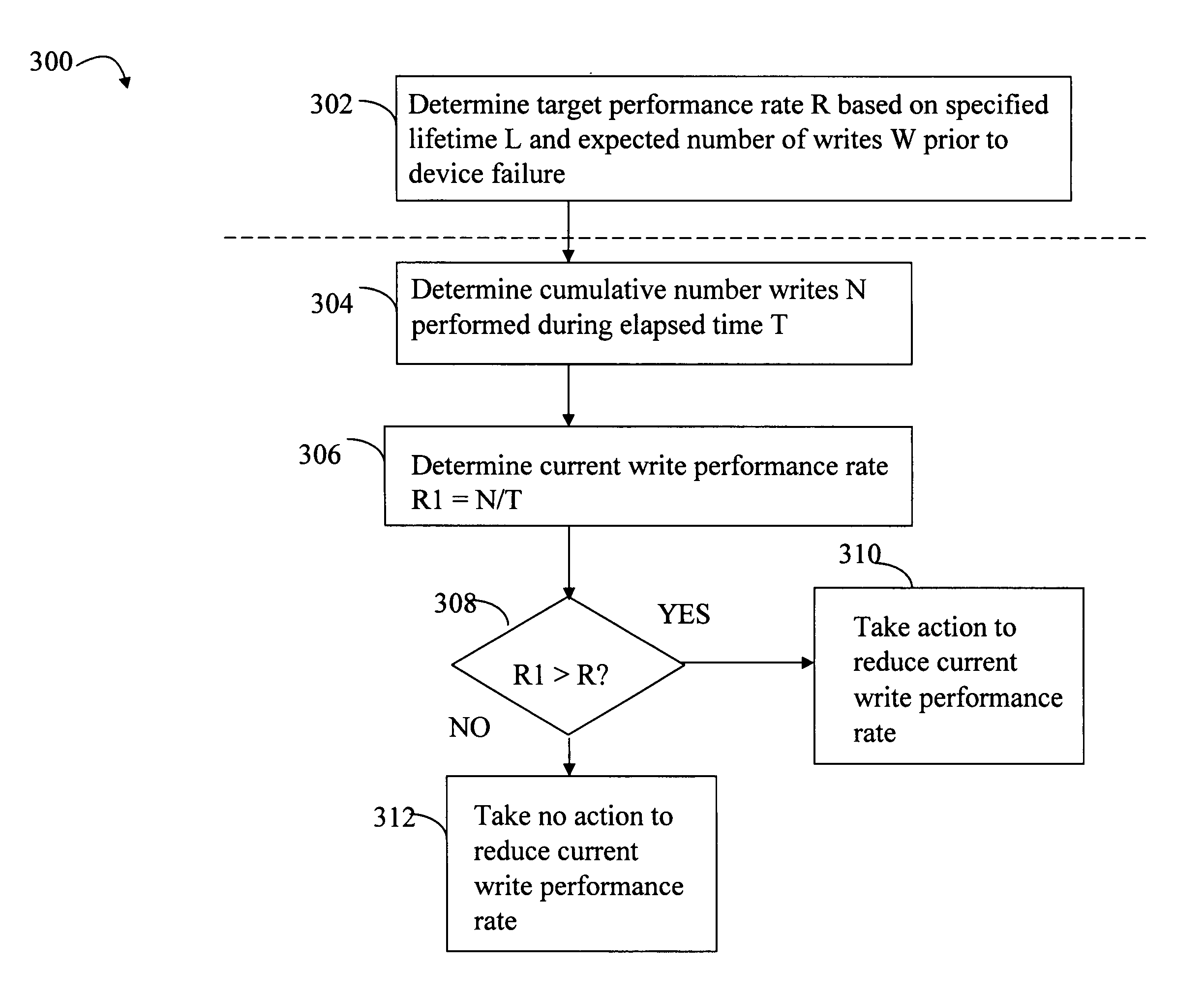
The patent describes a method for processing requests for a device, such as a flash memory device, by determining its expected usage and lifetime based on its first value and the number of writes or erasures it is expected to perform. The method includes determining a target rate of usage for the device and measuring its current rate of usage. If the current rate of usage is greater than the target rate, the method may perform an action to reduce the current rate, such as decreasing the rate at which erasures or writes are performed. The method may also include revising the first value to a revised first value based on the current rate of usage. The technical effect of this patent is to provide a more efficient and effective method for processing requests for devices, ensuring optimal performance and reliability.

Problems solved by technology

Different storage technologies, such as a flash memory device, may fail primarily due to wear out or usage, such as after performing a certain number of write cycles to store data on the flash memory device.
After performing the specified number of writes to the cell, that cell is expected to fail when attempting to subsequently write data thereto.
The foregoing is one example of a data storage technology and cause of wear out where the device may be expected to fail after a specified amount of usage.

Method used


Image

  • Techniques for obtaining a specified lifetime for a data storage device
  • Techniques for obtaining a specified lifetime for a data storage device
  • Techniques for obtaining a specified lifetime for a data storage device

Examples


Embodiment Construction

)

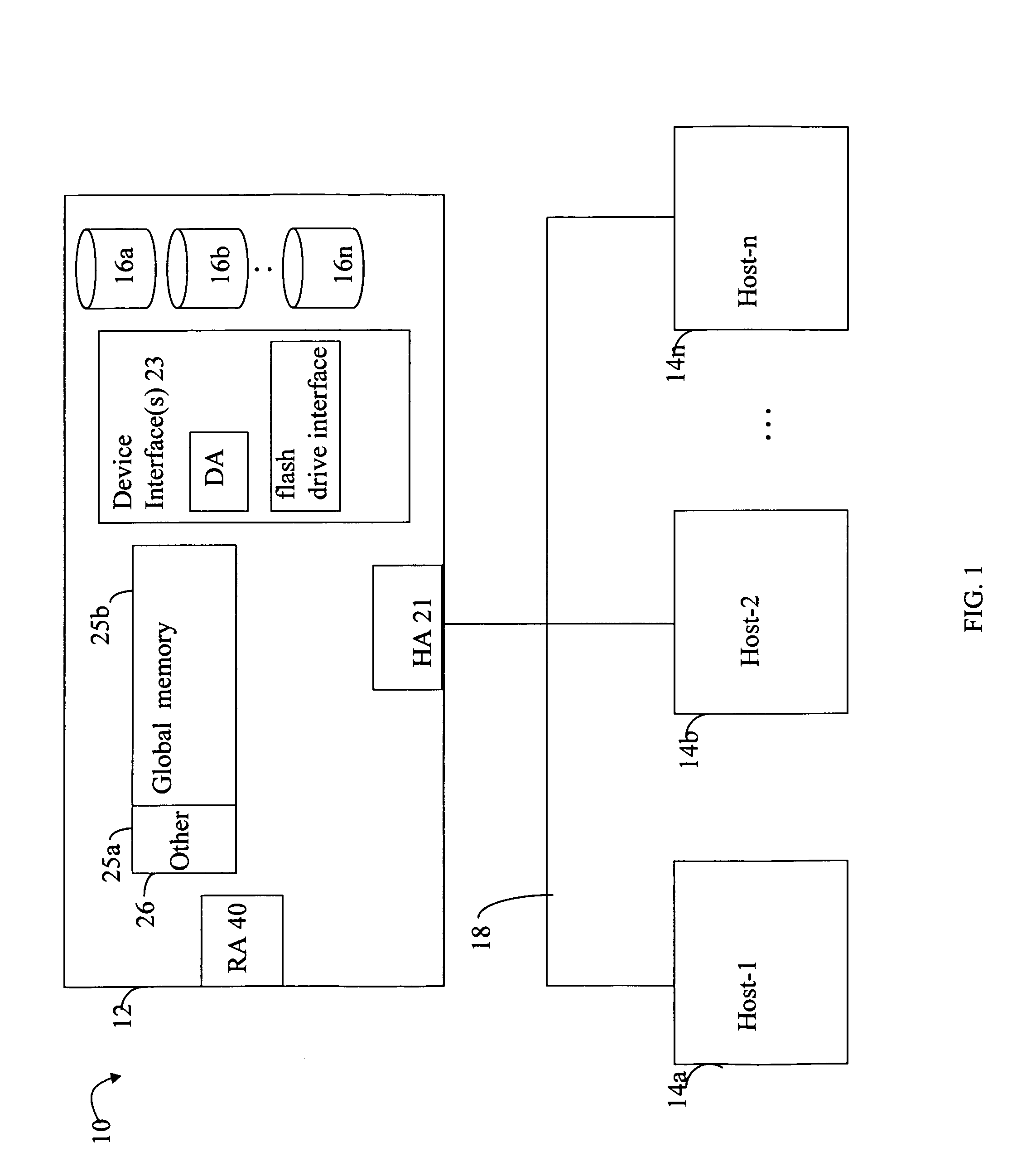
[0018]Referring to FIG. 1, shown is an example of an embodiment of a system that may be used in connection with performing the techniques described herein. The system 10 includes a data storage system 12 connected to host systems 14a-14n through communication medium 18. In this embodiment of the computer system 10, and the n hosts 14a-14n may access the data storage system 12, for example, in performing input / output (I / O) operations or data requests. The communication medium 18 may be any one or more of a variety of networks or other type of communication connections as known to those skilled in the art. The communication medium 18 may be a network connection, bus, and / or other type of data link, such as a hardwire or other connections known in the art. For example, the communication medium 18 may be the Internet, an intranet, network or other wireless or other hardwired connection(s) by which the host systems 14a-14n may access and communicate with the data storage system 12, and ...


PUM


Abstract

Described are techniques for processing requests for a device. One embodiment is directed to a method including receiving a first value indicating an expected usage of said device prior to failure of said device, receiving a second value indicated a specified lifetime of said device, said second value being in units of time, determining a target rate of usage for the device in accordance with said first value and said second value, determining a current rate of usage for the device, determining whether the current rate of usage is greater than the target rate of usage; and, if said current rate of usage is greater than the target rate of usage, performing an action to reduce the current rate of usage for the device.

Description

BACKGROUND[0001]1. Technical Field[0002]This application generally relates to data storage, and more particularly to techniques used in connection with obtaining a specified lifetime for a data storage device.[0003]2. Description of Related Art[0004]Computer systems may include different resources used by one or more host processors. Resources and host processors in a computer system may be interconnected by one or more communication connections. These resources may include, for example, data storage devices such as those included in the data storage systems manufactured by EMC Corporation. These data storage systems may be coupled to one or more host processors and provide storage services to each host processor. Multiple data storage systems from one or more different vendors may be connected and may provide common data storage for one or more host processors in a computer system.[0005]A host processor may perform a variety of data processing tasks and operations using the data st...

Claims


Application Information

Patent Timeline
Patent Type & Authority Patents(United States)
IPC IPC(8): G06F12/00G11C29/42
CPCG11C16/349G11C16/3436
Inventor CHILTON, KENDELL A.MORE, SACHIN
Owner EMC IP HLDG CO LLC
Learn More