Wind turbine erector

a technology of wind energy turbines and erectors, which is applied in the direction of machines/engines, forging/pressing/hammering apparatus, final product manufacturing, etc., can solve the problems of 38 trucks, high cost of erection, and high cost of cranes, so as to avoid the need for expensive cranes

Inactive Publication Date: 2011-09-06
VORHIES ROGER W
View PDF22 Cites 39 Cited by
  • Summary
  • Abstract
  • Description
  • Claims
  • Application Information

AI Technical Summary

Benefits of technology

[0009]A wind turbine erection device and methods for erecting wind turbines which avoids the need for using expensive cranes. The device and method employs a stacker unit for anchoring to the wind turbine foundation, a plurality of intermediate modules, and a mechanical actuator for raising the intermediate modules vertically. The stacker unit has a receptacle allowing for lateral sliding of intermediate modules inside of the stacker unit. In one embodiment, the stacker unit and intermediate modules also have at least one open side to allow for positioning of base, intermediate, and top tower sections within the stacker unit and stacked intermediate modules. A bridge crane section is initially placed on top of a plurality of stacked intermediate modules and is raised vertically as additional intermediate modules are added at the bottom. The stacking of intermediate modules allows the base, intermediate, and top tower sections to be winched into place using the crane, each being added on top of the other as the stacked intermediate modules increase to the necessary height.

Problems solved by technology

The large cranes used in the typical tower erection often are very expensive, renting for $88,000 / week or $240,000 / month plus maintenance.
Furthermore, 38 trucks are required to mobilize the cranes and cost $100,000 to bring into the site as well as out.
Those for the most part have been unsuccessful since they themselves are highly specialized and expensive equipment.
One problem with such devices is that strength of the structure is not increased as the device climbs the erected tower sections and the first tower section must still be set with a heavy duty crane.
Another problem is the expense and slowness of operation.

Method used


Image

  • Wind turbine erector
  • Wind turbine erector
  • Wind turbine erector

Examples


Embodiment Construction

[0022]For a better understanding of the present invention, specific exemplary embodiments according to present invention will be described in detail. The exemplary embodiments of the present invention have been set forth within the drawings and in the foregoing description and although specific terms are employed, these are used in the generically descriptive sense only and not used for the purposes of limitation. Changes in the form and proportion of parts as well as in substitution of equivalents are contemplated as circumstances may suggest or are rendered expedient without departing from the spirit and scope of the invention as further defined in the following description and claims.

[0023]Reference numerals will be used to indicate certain parts and locations throughout the Figures. The same reference numerals will be used to indicate the same or similar parts and locations throughout the Figures unless otherwise indicated.

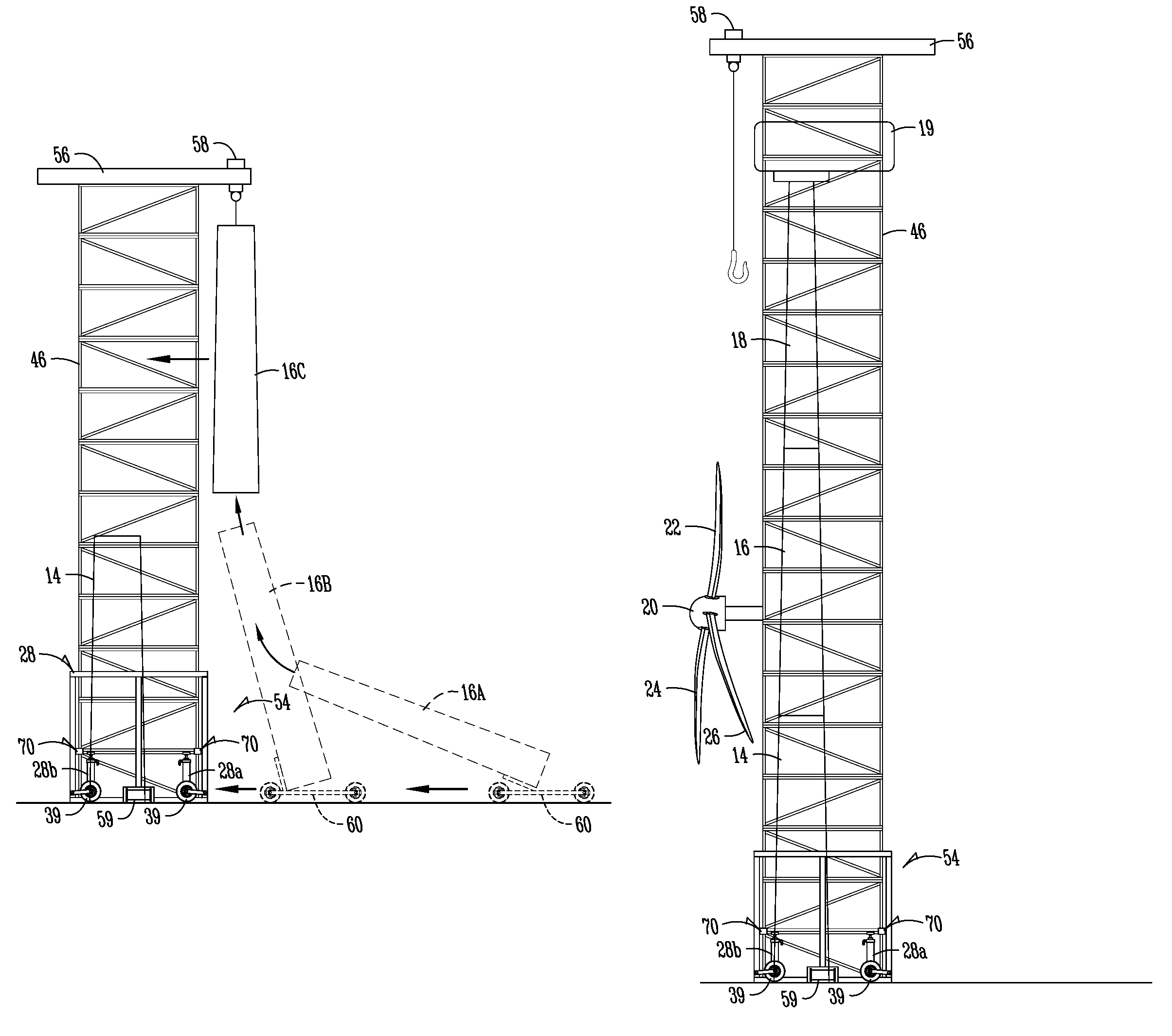
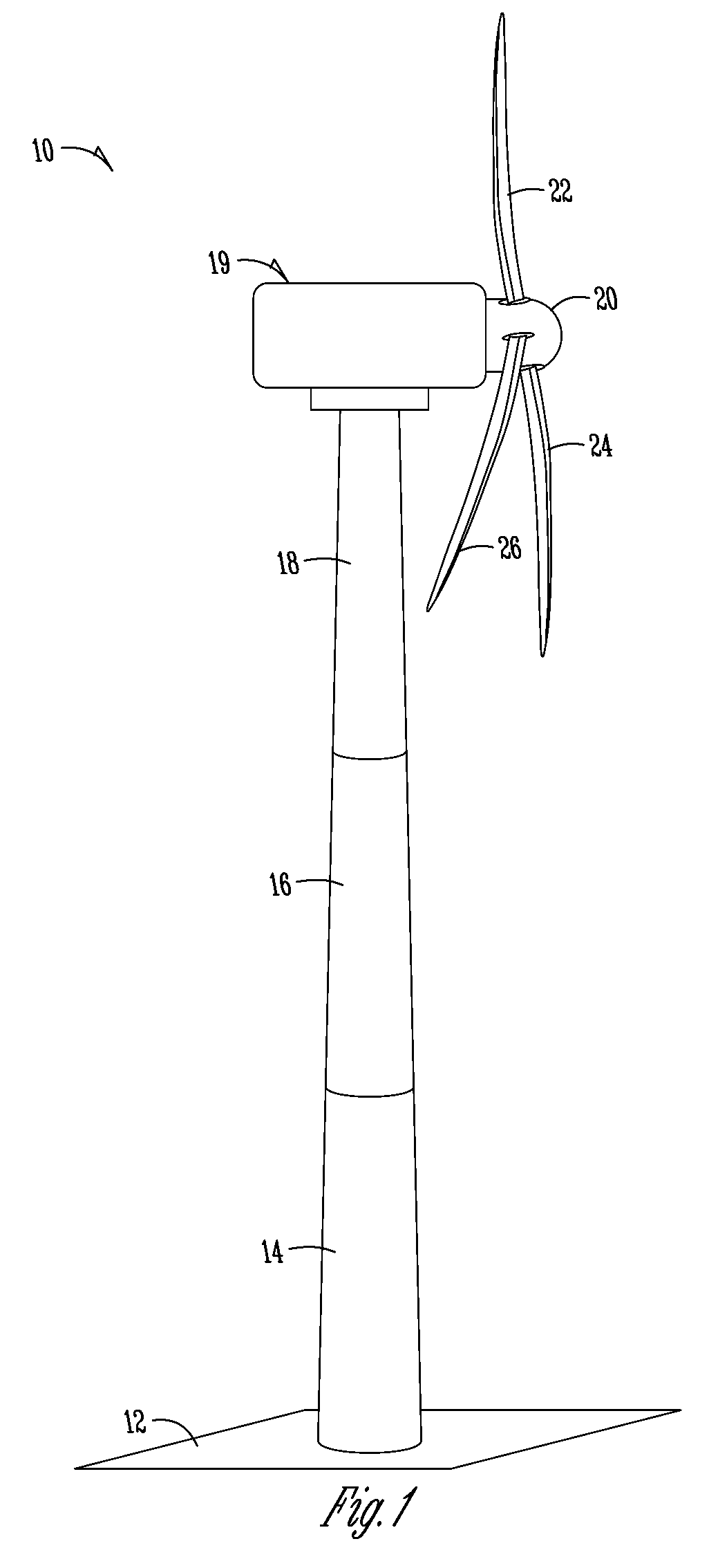
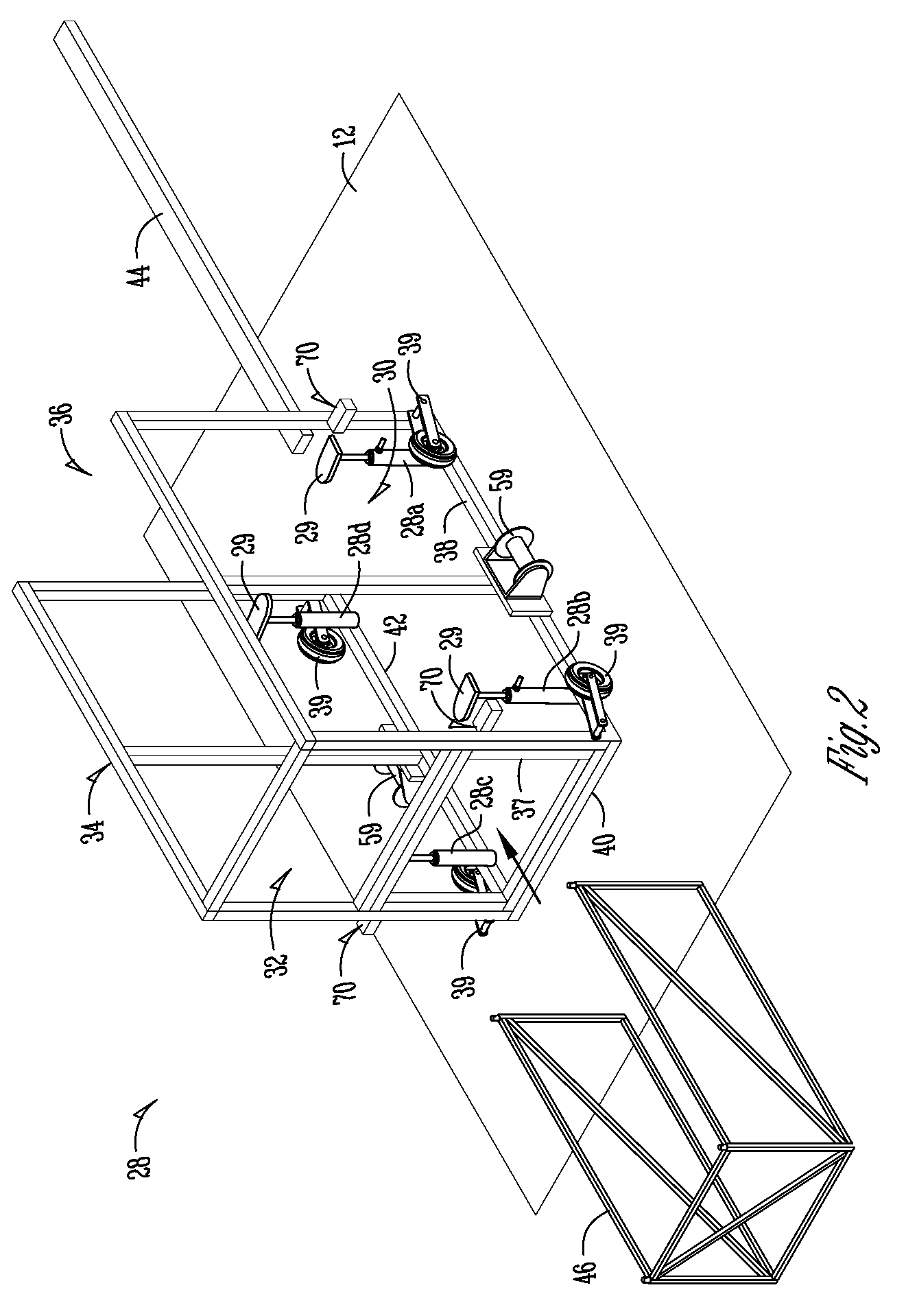
[0024]Referring to the drawings, the numeral 10 refers t...


PUM

PropertyMeasurementUnit
heightaaaaaaaaaa
heightaaaaaaaaaa
hub heightaaaaaaaaaa

Abstract

A wind tower erection device and method for erecting wind turbine towers which avoid the need for using expensive cranes. The device and method employs a stacker unit for anchoring to the wind turbine foundation, a plurality of intermediate modules, and a mechanical actuator for raising the intermediate modules vertically. The stacker unit has a receptacle allowing for lateral sliding of intermediate modules inside of the stacker unit. In one embodiment, the stacker unit has a receptacle for lateral sliding of intermediate modules inside of the stacker unit. The stacker unit and the intermediate modules each have at least one open side to for positioning of tower sections within the stacker unit and stacked intermediate modules. A bridge crane section is initially placed on top of the stacked intermediate modules. The bridge crane is raised vertically as additional intermediate modules are added at the bottom, thereby allowing wind tower sections to be winched into place using the crane, each being added on top of the other as the stacked intermediate modules increase to the necessary height.

Description

BACKGROUND OF THE INVENTION[0001]This invention relates to a method and system for erecting wind energy turbines that allow one to avoid the use of specialized and expensive cranes.[0002]Wind turbines are becoming ever more popular as the expense of electrical energy continues to increase. A typical wind turbine uses a rotary driven generator mounted atop a tower which can reach 80 meters or more in height. The next generation of towers will reach a height of 120 meters at the hub. In fact, 1.5 MW-2.5 W generators at 80 meters high are the staple of this industry because of what the highway systems can operate. The current method to erect towers with 80 meter hub height is with 3 cranes. A 50 ton crane is used for the blades and the hub to suspend them for pre-assembly prior to the use of a 450 ton crane to take the assembly to the 80 meter level. Prior to raising the assembly a 250 ton crane will set the first two tower sections. The first tower section is 90′ long with a 14′ diame...

Claims


Application Information

Patent Timeline
Patent Type & Authority Patents(United States)
IPC IPC(8): F03D11/04
CPCB66C17/06B66C23/185B66C23/207B66C23/283F03D1/001Y10T29/49321F05B2230/61Y02E10/728Y10T29/4932F03D13/10Y02E10/72Y02P70/50
Inventor VORHIES, ROGER W.HOAGE, JERARD B.
Owner VORHIES ROGER W
Why Eureka
Try Eureka