Formation evaluation using estimated borehole tool position

a technology of formation evaluation and tool position, which is applied in the field of geological exploration devices, systems and methods of wellbores, can solve the problems of inability to select the proper environmental correction to apply generally, lack of fe tool tracking, and conventional approaches that lack any way to extrapolate between (1) the eccentric and (2) the centered cases

Active Publication Date: 2011-09-13
BAKER HUGHES INC
View PDF24 Cites 8 Cited by
  • Summary
  • Abstract
  • Description
  • Claims
  • Application Information

AI Technical Summary

Problems solved by technology

However, the conventional approaches are not able to allow the selection of the proper environmental corrections to apply generally, lacking any way to track the FE tool center and direction with respect to the borehole center.
For a non-azimuthal FE tool, for example, the conventional approaches lack any way to extrapolate between (1) the eccentered and (2) the centered cases described above, even assuming constant FE tool rotation.
Similarly, for an azimuthal FE tool, where the diluting effects of the FE tool rotation may not appear, the conventional approaches lack any way to provide an absolute standoff correction correcting for the FE tool location and orientation in the borehole.

Method used


Image

  • Formation evaluation using estimated borehole tool position
  • Formation evaluation using estimated borehole tool position
  • Formation evaluation using estimated borehole tool position

Examples


Embodiment Construction

[0029]Illustrative embodiments of the present disclosure are described in detail below. In the interest of clarity, not all features of an actual implementation are described in this specification. It will of course be appreciated that in the development of any such actual embodiment, numerous implementation-specific decisions must be made to achieve the developers' specific goals, such as compliance with system-related and business-related constraints, which will vary from one implementation to another. Moreover, it will be appreciated that such a development effort might be complex and time-consuming, but would nevertheless be a routine undertaking for those of ordinary skill in the art having the benefit of the present disclosure.

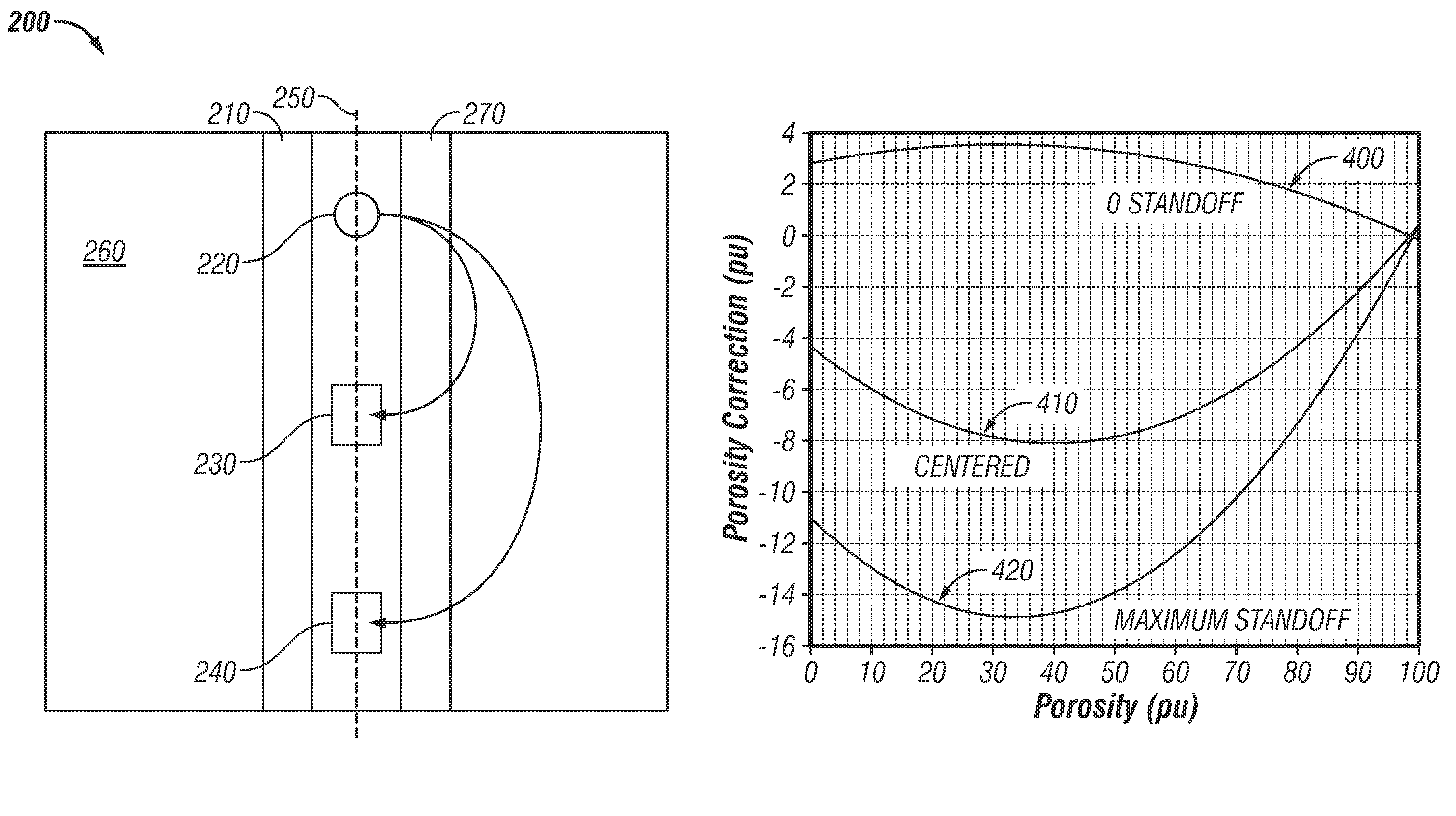
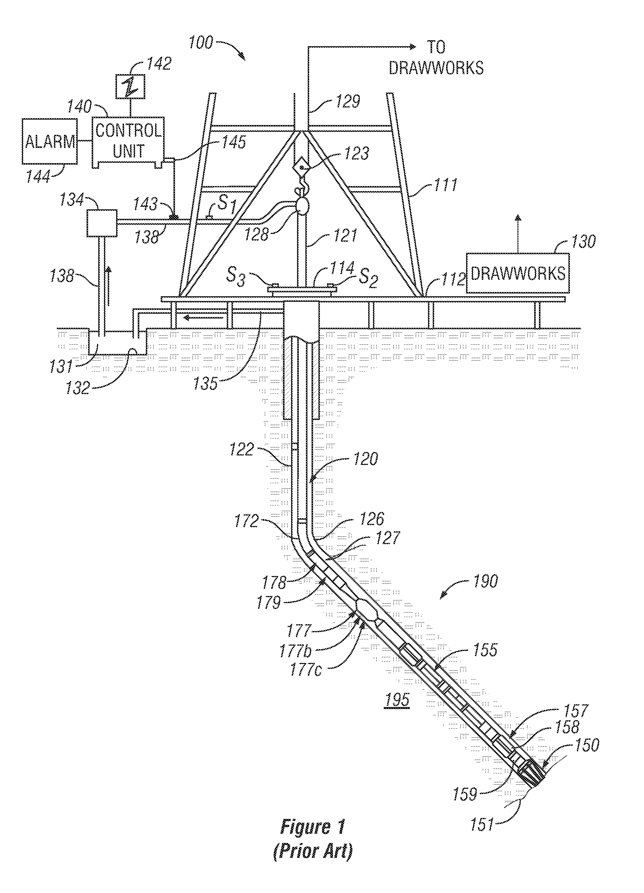
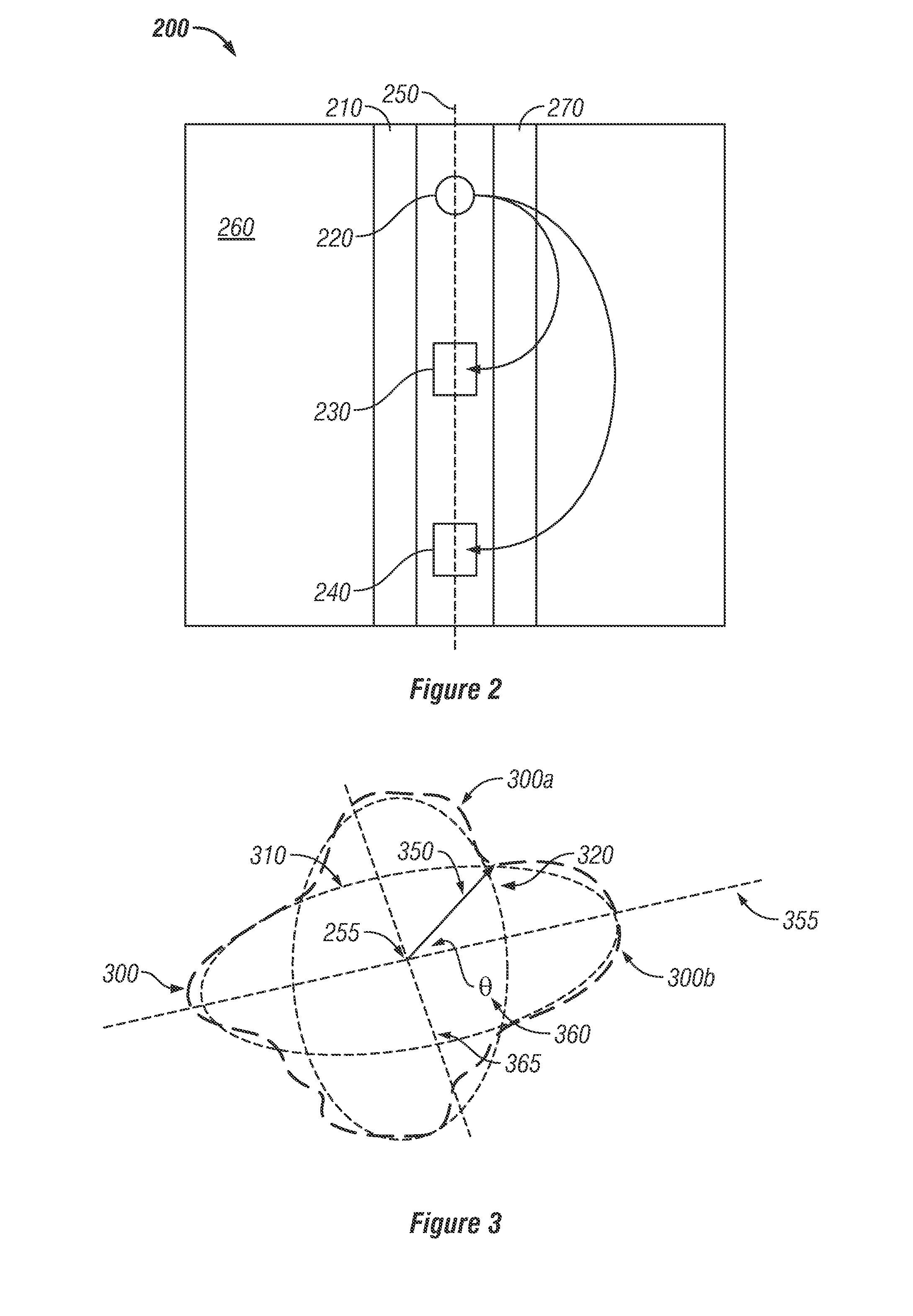
[0030]Referring first to FIG. 1, a schematic diagram is shown of a drilling system 100 useful in various illustrative embodiments, the drilling system 100 having a drillstring 120 carrying a drilling assembly 190 (also referred to as a bottomhole assembl...


PUM


Abstract

Caliper measurements made during rotation of an imager on a logging string are processed to estimate the location of the imager, and size and shape of the borehole. A piecewise elliptical fitting procedure may be used. These estimates may be used to correct measurements made by a standoff-sensitive formation evaluation sensor such as a neutron porosity tool. It is emphasized that this abstract is provided to comply with the rules requiring an abstract which will allow a searcher or other reader to quickly ascertain the subject matter of the technical disclosure. It is submitted with the understanding that it will not be used to interpret or limit the scope or meaning of the claims.

Description

CROSS-REFERENCES TO RELATED APPLICATIONS[0001]This application claims priority as a continuation-in-part of U.S. patent application Ser. No. 11 / 863,052 of Hassan et al, filed on Sep. 27, 2007, which claimed priority from U.S. Provisional Patent Application Ser. No. 60 / 847,948 filed on Sep. 28, 2006 and from U.S. Provisional Patent Application Ser. No. 60 / 849,962 filed on Oct. 6, 2006.TECHNICAL FIELD OF THE PRESENT DISCLOSURE[0002]The present disclosure relates generally to devices, systems, and methods of geological exploration in wellbores. More particularly, the present disclosure describes a device, a system, and a method useful for determining a downhole formation evaluation tool position in a borehole during drilling.BACKGROUND OF THE PRESENT DISCLOSURE[0003]A variety of techniques are currently utilized in determining the presence and estimation of quantities of hydrocarbons (oil and gas) in earth formations. These methods are designed to determine formation parameters, includ...

Claims


Application Information

Patent Timeline
Patent Type & Authority Patents(United States)
IPC IPC(8): E21B44/00G01V1/40
CPCE21B47/08G01V11/002G01V1/50
Inventor HASSAN, GAMAL A.KURKOSKI, PHILIP L.
Owner BAKER HUGHES INC
Why Eureka
Try Eureka