Rotary-valve and adsorption separation system

a separation system and rotary valve technology, applied in the field of rotary valves, can solve the problems of lowering or reducing the rotary speed

Inactive Publication Date: 2011-09-13
TEIJIN LTD +1
View PDF15 Cites 8 Cited by
  • Summary
  • Abstract
  • Description
  • Claims
  • Application Information

AI Technical Summary

Benefits of technology

[0006]The inventors of the present invention have found that when gas having the condensation property such as pressurized air containing moisture is connected to such a valve, liquid such as water is condensed due to the liquidized condensation phenomenon in the flow passage or the capillary condensation on the sliding surface of the valve, and if a small amount of liquid enters between the sliding surfaces, a surface tension temporarily becomes dominant to extremely rise the sliding resistance, resulting in the increase in rotary torque. While there are no problems if a motor having a rotary torque larger than such the increase in torque is used, in a system using a motor rotatable by a minimum torque for the purpose of minimizing a size and / or a weight of the system, there might be a problem in a high humidity environment in that the rotary speed is lowered or zero.

Problems solved by technology

While there are no problems if a motor having a rotary torque larger than such the increase in torque is used, in a system using a motor rotatable by a minimum torque for the purpose of minimizing a size and / or a weight of the system, there might be a problem in a high humidity environment in that the rotary speed is lowered or zero.

Method used


Image

  • Rotary-valve and adsorption separation system
  • Rotary-valve and adsorption separation system
  • Rotary-valve and adsorption separation system

Examples


example 1

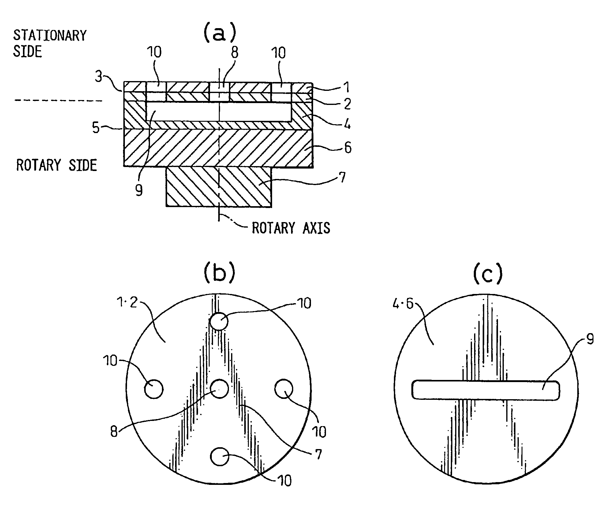
[0027]Example 1 of the inventive rotary valve will be described in accordance with the structure shown in FIG. 1. The rotary valve of Example 1 is a slidable valve for supplying air containing water vapor taken from atmosphere to a plurality of treatment processes, part of which outer layer including the sliding surfaces is made of hydrophobic material.

[0028]Rotary members 4, 6 and 7 are perpendicularly pushed onto stationary members 1, 2 by a reactive force of a spring not shown. The rotary members 4, 6 are bonded together via a bonding surface 5 to be one-piece. Similarly, the stationary members 1, 2 are bonded together via a bonding surface 3 to be one-piece.

[0029]One member 4 of the rotary members 4, 6 disposed on the sliding surface side is made of PTFE type resin. This PTFE type resin is PTFE resin added with carbon as filler, (which is H4C grade, manufactured by NIPPON PILLAR PACKING CO., LTD.) The other member 6 of the rotary members 4, 6 disposed opposite to the sliding sur...

example 2

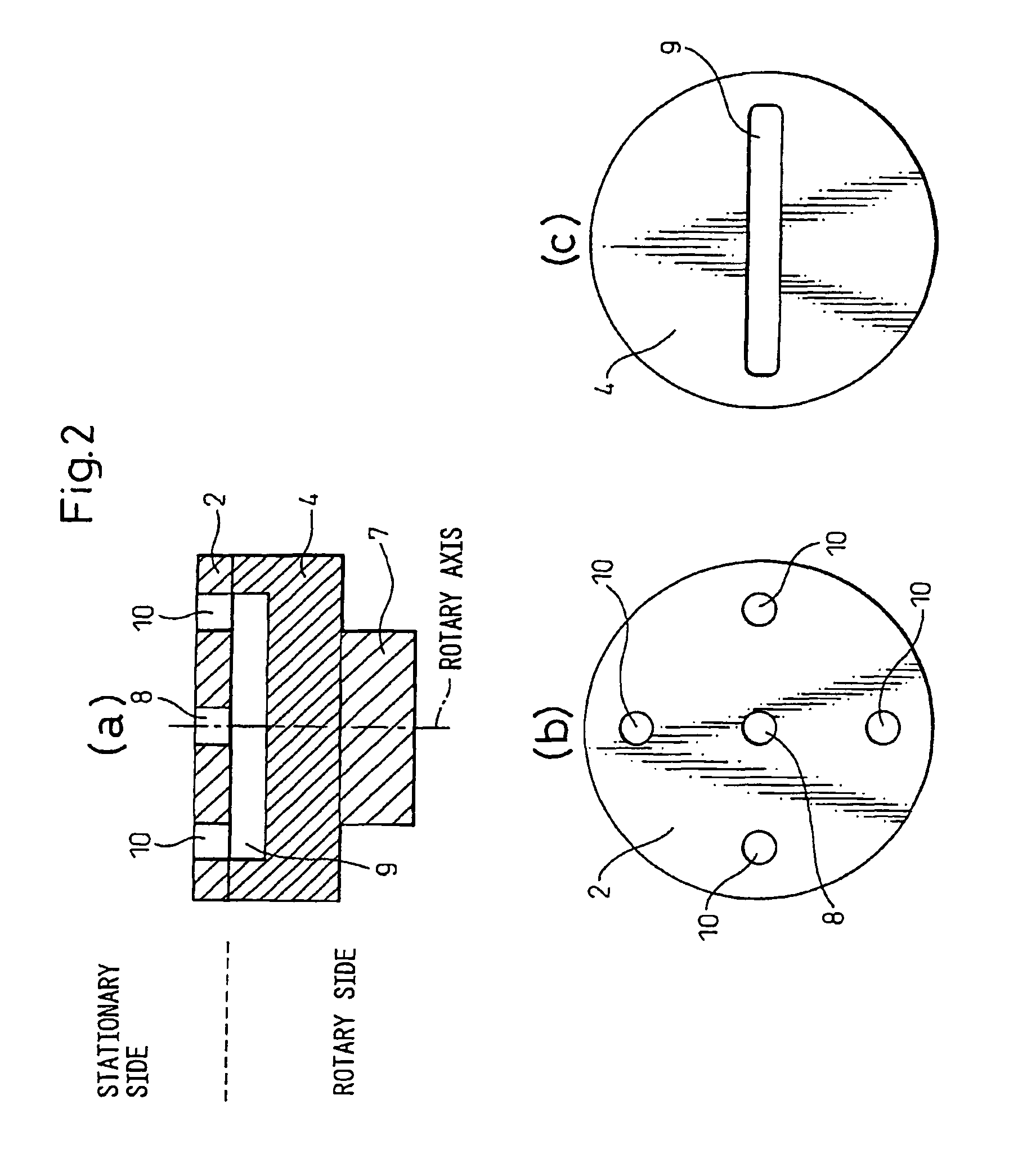
[0034]Next, Example 2 of the inventive rotary valve will be described in accordance with FIG. 2. In the rotary valve of Example 2, all of a surface layer section including the sliding surface for supplying air containing water vapor, taken from the atmosphere, to a plurality of treatment processes is made of hydrophobic material.

[0035]The stationary member 2 is made of a single material of PTFE type resin; in this Example, Y2A grade manufactured by NIPPON PILLAR PACKING CO., LTD. Also, the rotary member 4 is made of a single material of PTFE type resin; in this Example, H4C manufactured by NIPPON PILLAR PACKING CO., LTD. Other structures are the same as Example 1.

[0036]In the same manner as Example 1, the rotary valve of Example 2 is capable of carrying out a continuous operation for a long period in a stable state even if the condensation of water or occurs in an environment wherein the temperature and humidity of air containing water vapor taken from the atmosphere as well as the ...

modified examples

[0039]While Examples of the present invention were described above with reference to the attached drawings, the present invention should not be limited to the above-mentioned Examples 1 and 2, but includes various changes, modifications or alternations within a spirit or scope of the present invention. For example, in the respective Examples of the rotary valve described above, the rotary valve may be used for distributing treatment gas to a system including a plurality of adsorption tubes, reactors or dust collectors.

[0040]Also, by combining sliding members used in Examples 1 and 2 to be a one-piece structure as Example 1, the stationary member may consist of a hydrophobic member 2 on the sliding surface side and a high-rigidity member 1 bonded to the former opposite to the sliding surface side to be a one-piece structure as in Example 1, while the rotary member may be a single hydrophobic member 4 as in Example 2. Contrary to this, the stationary member may be a single hydrophobic...


PUM


Abstract

A rotary valve comprising sliding members for supplying treatment gas containing water vapor to a plurality of treatment processes is provided. The rotary valve comprises sliding members (1, 2; 4, 6), through which open flow passages (8, 9, 10), having sliding surfaces slidable to each other and a mechanical seal mechanism for switching the flow passages (8, 9, 10) while sealing fluid by preliminarily pressing the sliding surfaces, wherein the sliding surface of each sliding members (1, 2; 4, 6) is made of hydrophobic material (2, 4) different in hardness from the other.

Description

TECHNICAL FIELD[0001]The present invention relates to a rotary valve for switching a fluid passage by the mutual sliding rotary motion between a rotary member and a stationary member, and particularly to a rotary valve for switching a flow passage of a pressure swing adsorption (SPA) type oxygen concentrator for separating oxygen in air and supplying the same to a respiratory patient or others. The present invention also relates to an adsorption separation system using such a rotary valve.BACKGROUND ART[0002]Recently, there is the tendency in that patients suffered from respiratory diseases such as pulmonary emphysema or chronic bronchitis have increased. One of most effective treatments for such diseases is an oxygen inhalation therapy. On the other hand, an oxygen condenser for separating oxygen-condensed gas directly from air has been developed and gradually prevailed as a treatment device for the oxygen-inhalation therapy due to the convenience when used and the easiness of main...

Claims


Application Information

Patent Timeline
Patent Type & Authority Patents(United States)
IPC IPC(8): F16K11/074F16K3/08B01D53/047A61M16/10
CPCA61M16/10A61M16/20B01D53/0446A61M16/101F16K3/08F16K11/0743A61M2202/0208B01D53/047B01D2259/40005B01D2259/4533B01D2256/12F16K11/074B01D53/04
Inventor TAKEMASA, KENJIFUSE, TOSHIHIKOKUDARI, MITSURUNINOMIYA, MASANOBU
Owner TEIJIN LTD
Why Eureka
Try Eureka