High precision - automated celestial navigation system

a technology of automatic celestial navigation and high precision, applied in the direction of navigation instruments, instruments, navigation by astronomical means, etc., can solve the problems of gyro errors (attitude), accelerometer errors (position and velocity), and may not be available, so as to minimize the size and weight of payloads

Active Publication Date: 2021-02-04
TREX ENTERPRISES CORP
View PDF0 Cites 8 Cited by
  • Summary
  • Abstract
  • Description
  • Claims
  • Application Information

AI Technical Summary

Benefits of technology

[0012]Applicants' novel sheared-aperture automated dual-band telescope design permits an ultra-compact optical train, minimizing payload size and weight for the stabilized pointing mount. The above-deck sub-system weighs less than 100 pounds and fits within a one-half meter cube. Using two imaging sensors and two camera shutters, the HP-ACNS can independently and simultaneously detect both satellites and stars. When the pointing mount tracks the Satellite with one sensor, a second sensor with different shutter rate and shift-and-add image stabilization technique is used to obtain star images containing single or multiple short exposures.

Problems solved by technology

In some situations GPS may not be available.
It can be jammed or interfered with to provide false information.
However, gyro errors (attitude), accelerometer errors (position and velocity), and the “cross product” of acceleration and attitude errors accumulate over time.
However, a conventional star tracker on a moving platform has a limitation.
Since neither an accelerometer nor a tilt meter can discriminate between gravity force and acceleration, measurements of the local vertical on a moving platform are very difficult.
This places a fundamental limitation on utility of conventional star trackers for marine vessels and aircraft.

Method used


Image

  • High precision - automated celestial navigation system
  • High precision - automated celestial navigation system
  • High precision - automated celestial navigation system

Examples


Embodiment Construction

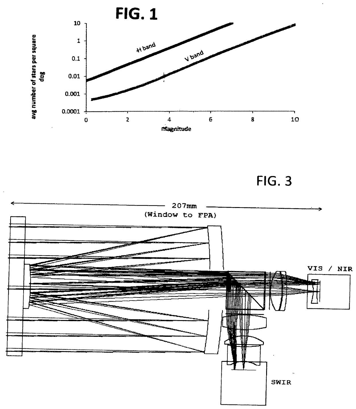
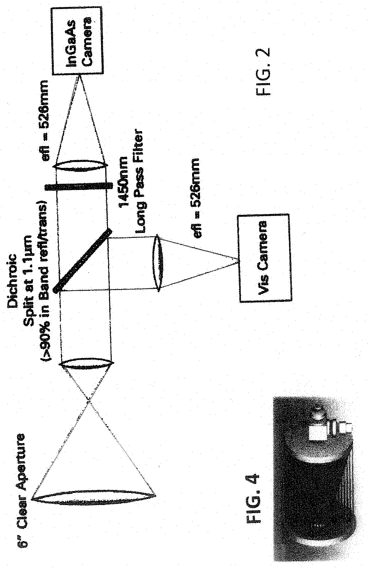
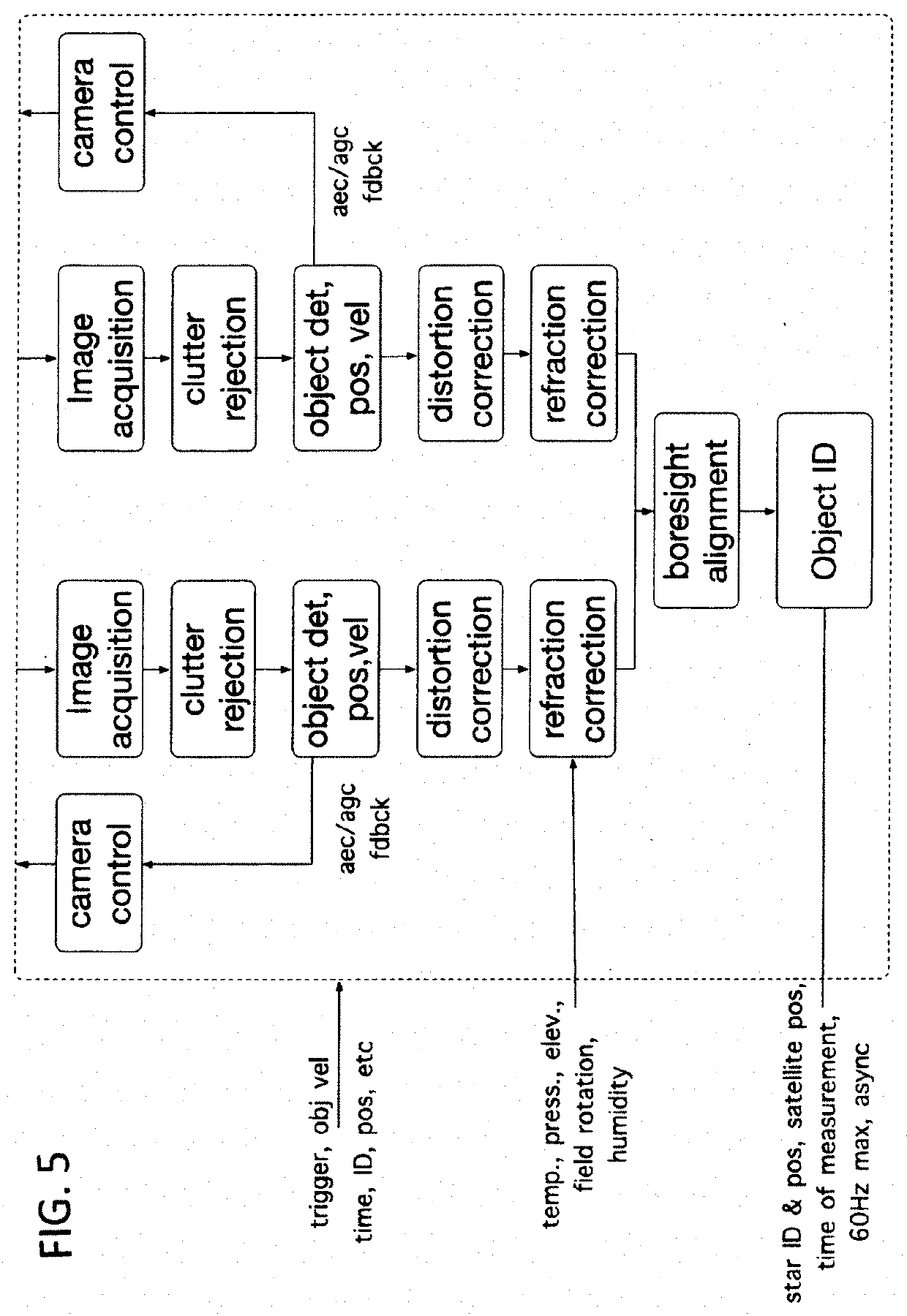
[0040]Preferred embodiments of the present invention include high precision, automated dual-band celestial navigation system for marine vessels with an above-deck optical payload mounted on a gyro-stabilized four-axis pointing platform, adapted to image satellites and nearby stars within field of view (FOV) of the telescope, both day and night and a dual-band optical system including a dichroic beam splitter adapted to separate light from the fields of view of the telescope into a visible light beam and a short wave infrared beam, a short wave infrared sensor adapted to monitor light from the short wave infrared beam and create images of stars within the telescope field of view and a visible light sensor adapted to monitor light from the visible light beam and create images of satellites within the telescope field of view. Preferred embodiments include independent camera shutters for each of the SWIR sensor and the visible light sensor. The optical payloads include a local inertial ...


PUM


Abstract

A dual-band (SWIR/visible) optical system operating based on Angles-Only Navigation technology. The SWIR module is optimized for imaging stars. The visible-light sensor is independently optimized for imaging satellites including GPS satellites at night. Preferred embodiment provides continuous high accuracy geo-position solutions day and night (including through the “midnight hole”, when solar-illuminated Low Earth Orbit (LEO) satellites are not available. Applicants have experimentally validated proposed system by imaging LEO satellites during terminator using a 1-inch diameter telescope and GPS satellites at night during midnight hole using a 5-inch telescope.

Description

CROSS REFERENCE TO PRIOR APPLICATIONS[0001]This application claims the benefit of Provisional Patent Application Ser. No. 764,374, filed Jul. 30, 2018BACKGROUND OF THE INVENTIONGPS[0002]The Global Positioning System (GPS) is a space-based satellite navigation system that provides location and time information in all weather conditions, anywhere on or near the Earth where there is an unobstructed line of sight to four or more GPS satellites. The system provides critical capabilities to military, civil and commercial users around the world. It is maintained by the United States government and is freely accessible to anyone with a GPS receiver.[0003]The GPS project was developed in 1973 to overcome the limitations of previous navigation systems, integrating ideas from several predecessors, including a number of classified engineering design studies from the 1960s. GPS was created and realized by the U.S. Department of Defense (DoD) and was originally run with 24 satellites. It became f...

Claims


Application Information

Patent Timeline
Patent Type & Authority Applications(United States)
IPC IPC(8): G01C21/02G01C21/20G01S3/786G01S19/39G02B23/24
CPCG01C21/025G01C21/203G02B23/2407G01S19/393G01S3/7867G01S5/16G02B23/04G02B23/06G02B27/1013G02B27/141
Inventor BELENKII, MIKHAILBRINKLEY, TIMOTHY
Owner TREX ENTERPRISES CORP
Why Eureka
Try Eureka