Stimulated brillouin scattering optical amplifier

a technology of optical amplifier and brillouin, which is applied in the direction of laser using scattering effects, electrical apparatus, laser details, etc., can solve the problems of limited operation and implementation, inability to remove inherent inefficiencies and engineering difficulties, and immediate distortion of the efficiency of the optical amplifier, so as to reduce the amount of engineering and design, the overall system operation is more energy efficient, and the effect of less energy loss

Active Publication Date: 2005-05-10
THE BOEING CO
View PDF5 Cites 9 Cited by
  • Summary
  • Abstract
  • Description
  • Claims
  • Application Information

AI Technical Summary

Benefits of technology

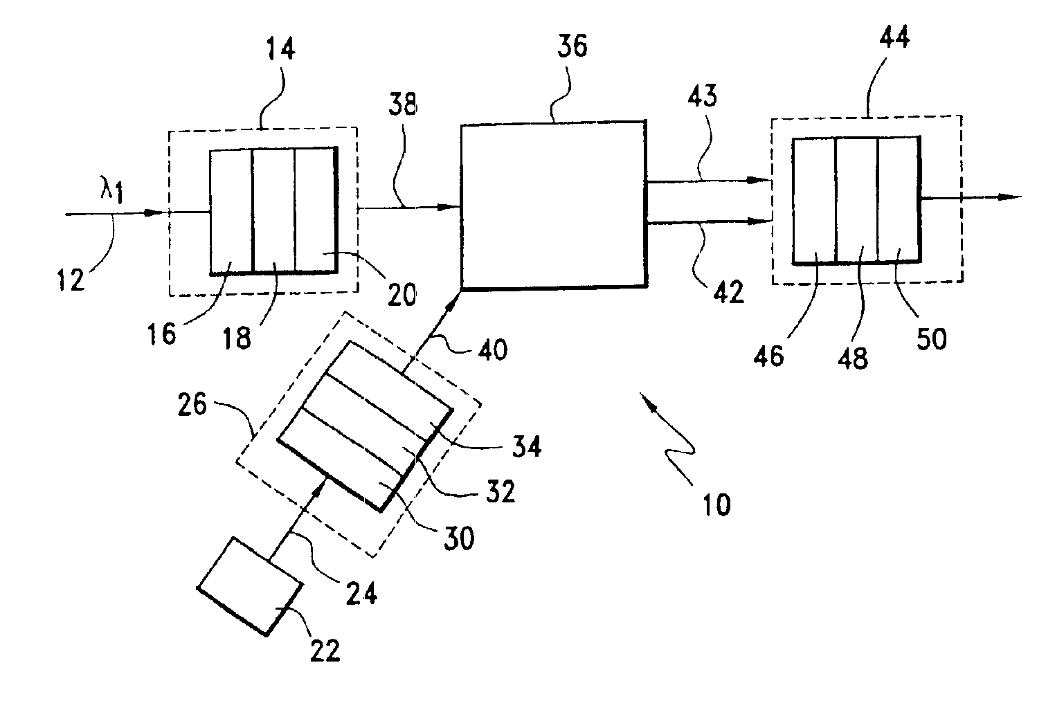
[0007]In a broad aspect, the stimulated Brillouin scattering optical amplifier of the present invention includes a first control optics assembly, a driver element, a second control optics assembly, a Brillouin active medium, and egressing optics. The first control optics assembly receives an incoming laser beam and adjusts that incoming laser beam in accordance with first desired wavelength, polarization and beam propagation parameters. A driver element produces a driver laser beam. A second control optics assembly receives the driver laser beam and adjusts that driver laser beam in accordance with second desired wavelength, polarization and beam propagation parameters. A Brillouin active medium receives an output from the first control optics assembly and an output from the second control optics assembly. The Brillouin active medium provides a non-linear optical interaction between the outputs such that the incoming laser beam is amplified producing an amplified Brillouin active medium output laser beam and a depleted driver laser beam. Egressing optics receives the amplified Brillouin active medium output laser beam and the depleted driver laser beam. The egressing optics controllably transmits the amplified Brillouin active medium output laser beam in accordance with third desired wavelength, polarization, and beam propagation parameters and prevents transmission of the depleted driver laser beam. The output of the egressing optics includes an amplified egressing optics output laser beam.
[0008]The use of Brillouin scattering allows parametric amplification of a weak signal with considerably less energy loss to the excitation-coupling medium than Raman scattering. This makes the overall system operation more energy efficient. It reduces the amount of engineering and design necessary to remove the large amount of waste heat associated with the Raman process. As a result, the hardware associated with the use of this amplifier in an optical system, such as an optical communication system, minimizes volume and weight. Furthermore, it provides enhanced energy efficiency.

Problems solved by technology

Use of Raman scattering; however, has limitations in its operation and implementation.
That material excitation causes inherent inefficiencies and engineering difficulties that cannot be removed.
Furthermore, this material wave eventually couples its energy into thermal excitations within the media, so that it contributes to waste heat in the process.
This heat can lead to immediate distortions in the efficiency of the optical amplifier and long-term deterioration of the amplifier medium itself.
Considerable engineering must take place in the optical design to handle this problem, causing the system to be bulkier and heavier than it might be otherwise.
The inherent difficulty with Raman scattering is that the material excitation itself is a high energy excitation.
Consequently, 10% of the pump beam will be lost to the material excitation, even if the optical system is lossless otherwise.
For high power long term operation, this is a considerable loss.

Method used


Image

  • Stimulated brillouin scattering optical amplifier
  • Stimulated brillouin scattering optical amplifier
  • Stimulated brillouin scattering optical amplifier

Examples


Embodiment Construction

[0011]Referring to the drawings and the characters of reference marked thereon, FIG. 1 illustrates a preferred embodiment of the present invention, designated generally as 10. An incoming laser beam 12 is received by a first control optics assembly, designated generally as 14. The laser beam, λ1, may be generally described as an electromagnetic or light beam with a single narrow wavelength in the optical regime (0.1-10 microns), which is propagating in a uniform well-defined direction, made possible by its coherence properties. The laser beam could represent an image or could be a digitally encoded optical beam for data transmission.

[0012]The first control optics assembly 14 adjusts the incoming laser beam in accordance with first desired wavelength, polarization and beam propagation parameters. These parameters can include, for example, precise wavelength filtering to the expected signal wavelength, the optical bandwidth of the incoming signal, or the polarization of the light. The...


PUM


Abstract

The stimulated Brillouin scattering optical amplifier includes a first control optics assembly, a driver element, a second control optics assembly, a Brillouin active medium, and egressing optics. The first control optics assembly receives an incoming laser beam and adjusts that incoming laser beam in accordance with first desired wavelength, polarization and beam propagation parameters. A driver element produces a driver laser beam. A second control optics assembly receives the driver laser beam and adjusts that driver laser beam in accordance with second desired wavelength, polarization and beam propagation parameters. A Brillouin active medium receives an output from the first control optics assembly and an output from the second control optics assembly. The Brillouin active medium provides a non-linear optical interaction between the outputs such that the incoming laser beam is amplified producing an amplified Brillouin active medium output laser beam and a depleted driver laser beam. Egressing optics receives the amplified Brillouin active medium output laser beam and the depleted driver laser beam. The egressing optics controllably transmits the amplified Brillouin active medium output laser beam in accordance with third desired wavelength, polarization, and beam propagation parameters and prevents transmission of the depleted driver laser beam. The output of the egressing optics includes an amplified egressing optics output laser beam.

Description

BACKGROUND OF THE INVENTION[0001]1. Field of the Invention[0002]This invention relates to optical amplifiers and more particularly to an optical amplifier that uses stimulated Brillouin scattering for providing optical amplification.[0003]2. Description of the Related Art[0004]To this point, optical signal amplifiers have been dominated by Raman amplifiers. For example, U.S. Pat. No. 3,414,354, issued to E. H. Siegler Jr., entitled Raman Spectrometers, is a seminal publication disclosing the use of stimulated Raman scattering, to provide optical amplification. In a later example, U.S. Pat. No. 3,515,897, issued to W. H. Culver, discloses a design for implementing stimulated Raman scattering as an amplifier.[0005]Use of Raman scattering; however, has limitations in its operation and implementation. Examination of the equations that govern stimulated Raman scattering break down into two terms. The first term is associated with the wave that is being amplified, also known as the Stokes...

Claims


Application Information

Patent Timeline
Patent Type & Authority Patents(United States)
IPC IPC(8): H01S3/00H01S3/30H04B10/17
CPCH04B10/2916H01S3/30
Inventor HUNT, JEFFREY H.ATMUR, ROBERT J.
Owner THE BOEING CO
Why Eureka
Try Eureka