Pulper rotor and assembly

Inactive Publication Date: 2005-10-13
THERMO BLACK CLAWSON
View PDF42 Cites 9 Cited by
  • Summary
  • Abstract
  • Description
  • Claims
  • Application Information

AI Technical Summary

Benefits of technology

[0014] This invention provides an improved pulper, mixer or defibering, rotor having a spar ring attached to a hub of the rotor with a series of curved vanes projecting from the spar ring. The curved vanes have a constant vane face angle relative to radians immediately adjacent one another and extending outward from the hub of the

Problems solved by technology

Thus, the pulp, or other material being mixed, in conventional straight vane rotor systems tend to be ineffectively directed out of contact with the vane faces 17a and out of the rotary path of vanes 17, resulting in a more time-consuming mixing of the materials being required in order to achieve a desired defibering, for example, effect.
The additional mixing time due to the inefficiencies of straight vane rotors requires additional power consumption to operate the rotor until the desired defibering effect on the materials is achieved.
Further, the bluntness of the leading edge of straight vane face 17a subjects the vane faces 17a to considerable wear as mixing of materials occurs.
Further, the requirement of welding wear plates onto the vanes 17 limits the materials that can be used to those compatible with the underlying material chosen for the vane.
Such compatibility requirements may limit the choice of vane materials to those that are generally not the most wear-resistant type materials in order for the wear plates to be successfully welded o

Method used


Image

  • Pulper rotor and assembly
  • Pulper rotor and assembly
  • Pulper rotor and assembly

Examples


Embodiment Construction

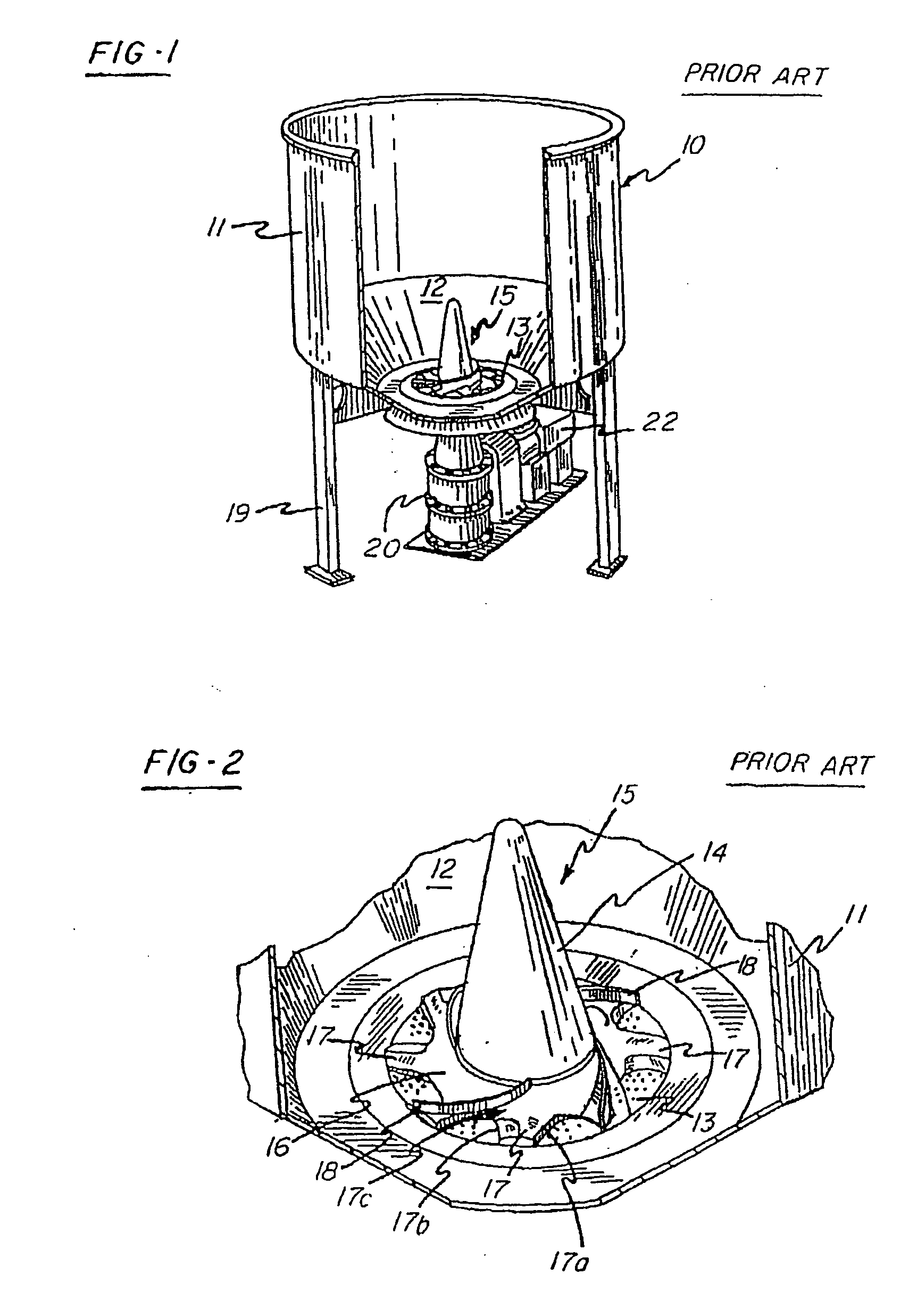
[0031] The conventional pulper tub, or vat, 10 shown in FIG. 1 shows generally the type of pulper tub, or vat, 10 with which the various exemplary embodiments of the improved pulper, mixing or defibering, rotor 35 of the invention described herein is intended to be used. Accordingly, like numerals are used, where possible, in describing the various exemplary embodiments of the invention when referring to features translatable with those of the conventional pulper of FIG. 1.

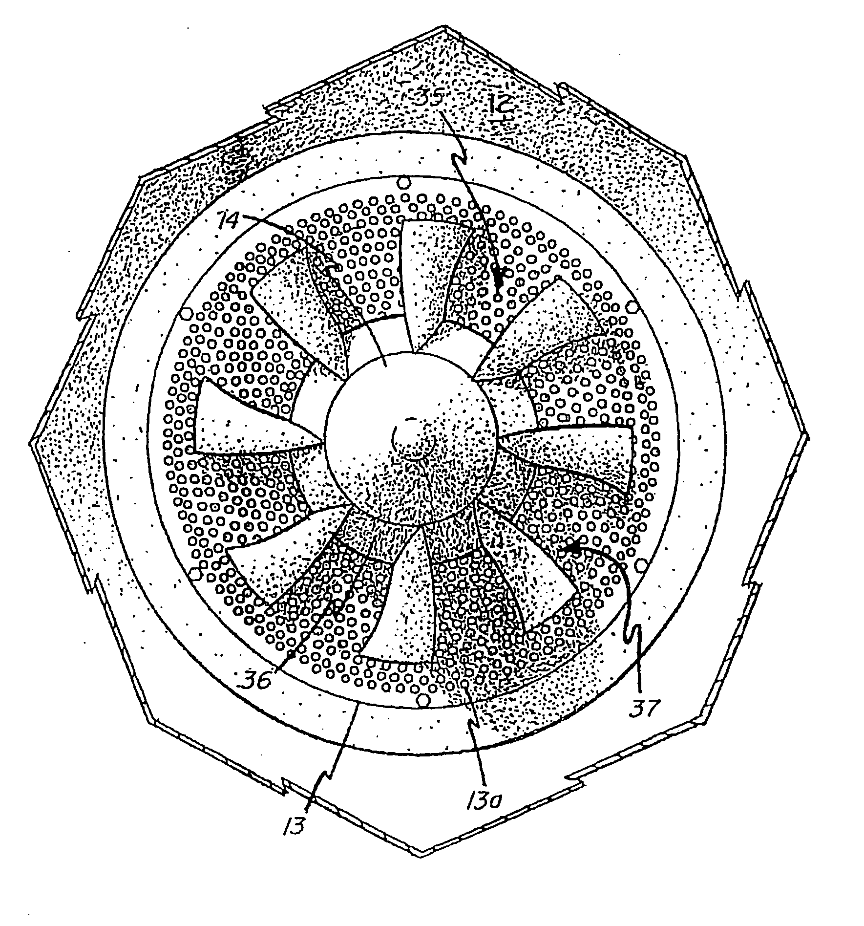
[0032]FIG. 4 shows one exemplary embodiment of the improved pulper, mixer or defibering, rotor 35 of the invention. The pulper, mixer or defibering, rotor 35 includes a spar ring 36 that supports a plurality of vanes 37. The vanes 37 extend generally radially outwardly from the spar ring 36 towards an outer circumference of the perforated bed-plate 13. The spar ring 36 is mounted about a hub 14 at the center of the bed-plate 13. The pulper, mixer or defibering, rotor 35 may be driven by a conventional gearing and...


PUM

PropertyMeasurementUnit
Angleaaaaaaaaaa
Angleaaaaaaaaaa
Lengthaaaaaaaaaa

Abstract

An improved pulper, mixer or defibering, rotor having a spar ring attached to a hub of the rotor with a series of curved vanes projecting from the spar ring. The curved vanes have a vane face and a trailing edge. The trailing edge may be unitary and integral with the vane, or may be segmented in combination with trailing edge portion provided on an underlying spar stub to which the vanes are attached. The hydrodynamic suction created by the trailing edge is enhanced by the addition of a dam at the vane tip end of the trailing edge zone. The vanes have a constant vane face angle relative to radians extending outward from the hub of the rotor. As a result of the constant vane face angle the pulp, or other materials, mixed by the vanes during rotation of the rotor are more consistently in contact with the vanes during rotation of the rotor. The vanes are also streamlined to reduce hydrodynamic drag especially at the vane tips where speed and therefore drag potential are at their highest levels. As a result, increased circulation and pumping effects with minimal power requirements are achieved. The vanes may be made of high wear resistant materials and are easily accessible for maintenance, repair or replacement.

Description

CROSS-REFERENCE TO RELATED APPLICATION [0001] This application claims the priority benefit of U.S. Provisional Patent Application 60 / 440,532 filed Jan. 16, 2003.BACKGROUND OF THE INVENTION [0002] 1. Field of Invention [0003] This invention relates to an improved pulper or mixer rotor with increased pumping and defibering capacities, reduced power requirements, easier maintenance and interchangeability of parts, and improved wear resistance. [0004] 2. Description of Related Art [0005]FIG. 1 shows a conventional pulping, mixing, or defibering apparatus, which generally includes a vat, or tub, 10 formed of side wall 11 and bottom wall 12. In the center of the bottom wall 12 is a perforated bed-plate 13. The bed-plate 13 permits draining of pulped paper stock, for example, after a pulping operation is completed. A rotor 15 for circulating the paper stock, for example, or other material, is mounted on a hub 14 in the center of the bed-plate 13. Supports 19 stabilize the pulping tub, or v...

Claims


Application Information

Patent Timeline
IPC IPC(8): B02C23/36D21B1/34
CPCD21B1/347
Inventor EGAN, JOHN J. IIIGREIER, DONALD J.
Owner THERMO BLACK CLAWSON
Why Eureka
Try Eureka