Rolling device and using method thereof

a technology of rolling device and rolling element, which is applied in the direction of roller bearings, mechanical equipment, rotary machine parts, etc., can solve the problems of reducing the dimensions of rolling elements, reducing so as to reduce the frictional resistance of rolling elements in the load area, reduce the frictional resistance, and prevent the effect of rolling elements from jostling

Active Publication Date: 2014-07-22
COO SPACE CO LTD
View PDF22 Cites 2 Cited by
  • Summary
  • Abstract
  • Description
  • Claims
  • Application Information

AI Technical Summary

Benefits of technology

[0007]However, even if the supporting cage in Patent Document 1 is used, sliding friction is still generated between rolling elements and the supporting cage, which may cause increase in rotary torque and breakage of the supporting cage. Moreover, the supporting cage occupies space, which reduces dimensions of the rolling elements and restricts a load capacity.
[0011]In accordance with a third aspect of the present invention, the area of the transfer path in which the frictional force acting between one of the transfer grooves of the transfer path and the rolling element is greater than the frictional force acting between the other transfer groove and the rolling element has smaller rigidity in a direction perpendicular to a transferring direction than rigidity in other part of the transfer path or a greater clearance between the transfer grooves than a clearance in other part to thereby form a no-load area in which the rolling elements are gently pinched between the transfer grooves.
[0017]According to the present invention, after rolling elements come in contact with each another and intervals between the rolling elements are made uniform on a contact point changing path, predetermined intervals are created and the rolling elements enter a load area. Therefore, jostling of the rolling elements in the load area can be prevented without using the supporting cage and an increase in frictional resistance caused by the jostling can be suppressed. Moreover, space that otherwise would be occupied by the supporting cage can be allocated to the rolling elements to increase the load capacity and the rolling elements are unconstrained by an environment created by a material of the supporting cage. Even if the supporting cage is provided, predetermined intervals are created after the rolling elements come in contact with the supporting cage and intervals between the rolling elements and the supporting cages are made uniform on the contact point changing path. Therefore, positions of the rolling elements with respect to the supporting cage are made uniform and jostling of the rolling elements through the supporting cage can be suppressed.

Problems solved by technology

However, even if the supporting cage in Patent Document 1 is used, sliding friction is still generated between rolling elements and the supporting cage, which may cause increase in rotary torque and breakage of the supporting cage.
Moreover, the supporting cage occupies space, which reduces dimensions of the rolling elements and restricts a load capacity.

Method used


Image

  • Rolling device and using method thereof
  • Rolling device and using method thereof
  • Rolling device and using method thereof

Examples


embodiment 1

[0032]A rolling device of the present invention will be described below in detail with reference to the accompanying drawings.

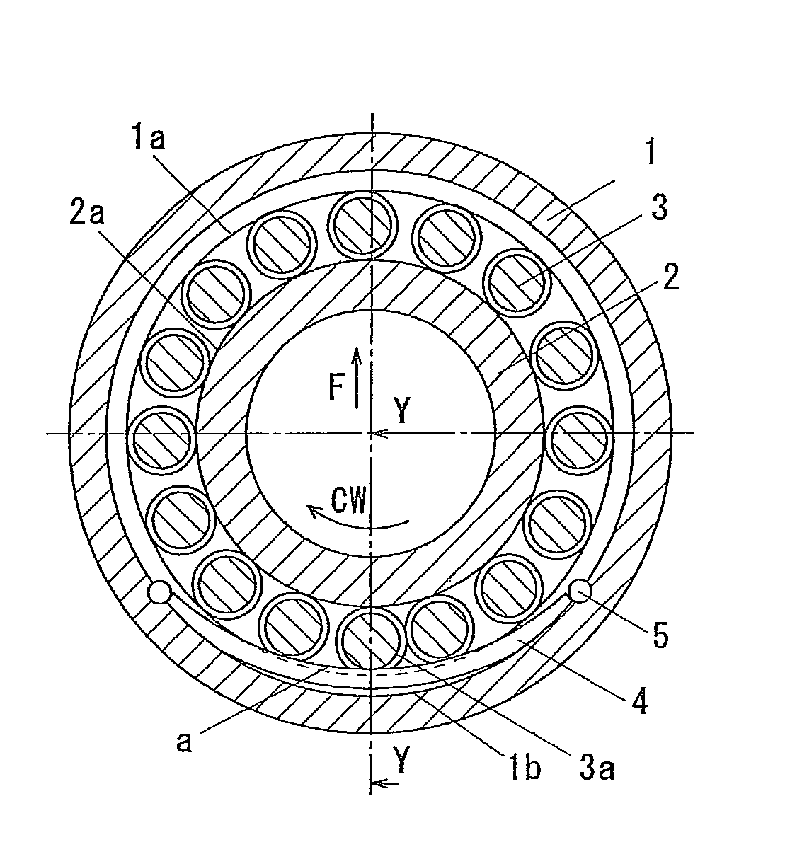
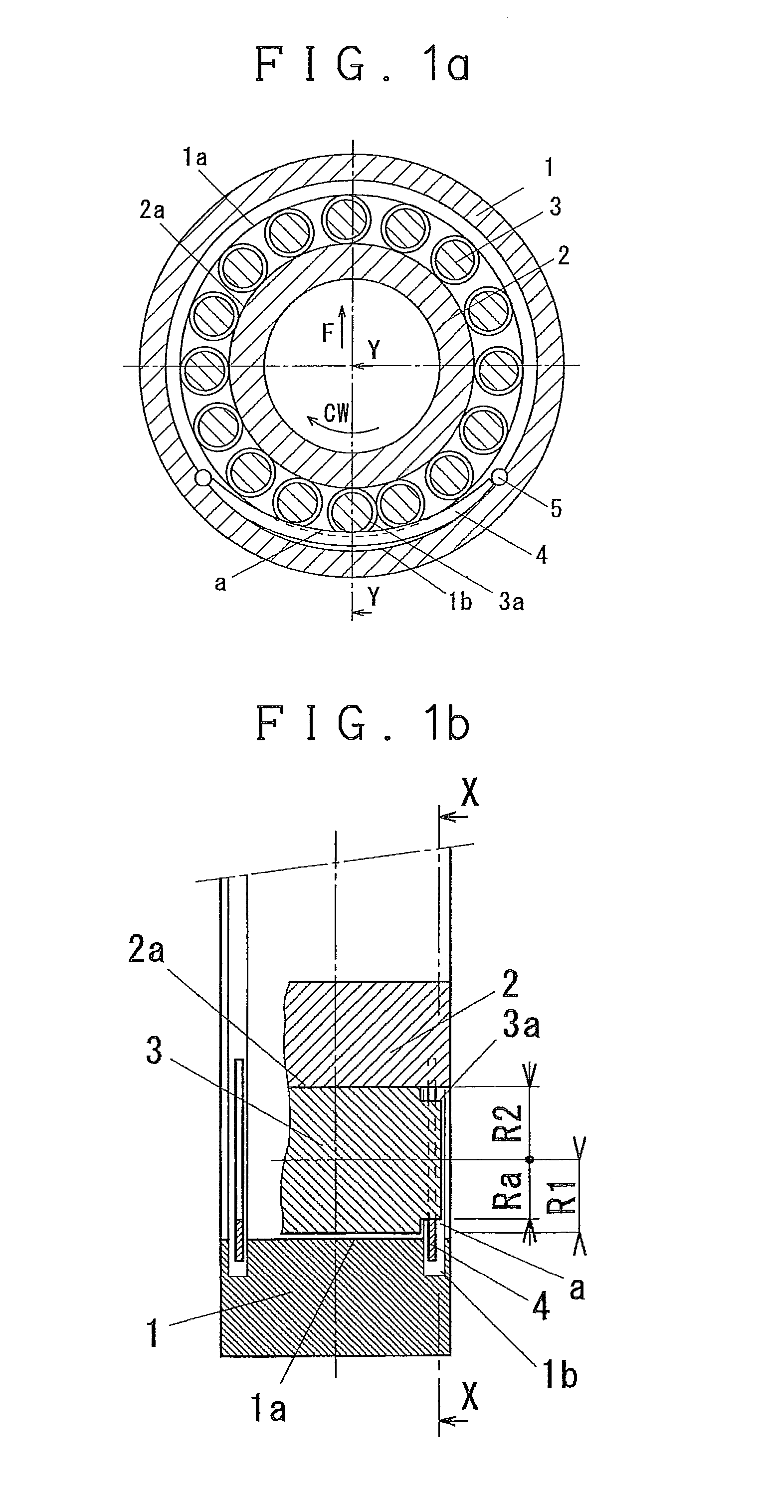
[0033]FIGS. 1a and 1b show a roller bearing of an embodiment of the present invention. FIG. 1a is a sectional view along line X-X in FIG. 1b. FIG. 1b is a sectional view along line Y-Y in FIG. 1a. The roller bearing includes an outer ring 1 having a transfer groove 1a, or first transfer groove 1a, on an inner side, an inner ring 2 having a transfer groove 2a, or second transfer groove 2a on an outer side, and a plurality of rollers 3 rollably inserted between the transfer grooves under a pre-load. Each of the rollers 3 is provided at opposite ends thereof with stepped portions 3a having smaller diameters and higher surface roughness in a rotating direction than the transfer groove 2a. The outer ring 1 has grooves 1b on opposite sides of the transfer groove 1a, decelerating plates 4 are fitted in the grooves, and opposite ends of the decelerating plates 4 are ...

embodiment 2

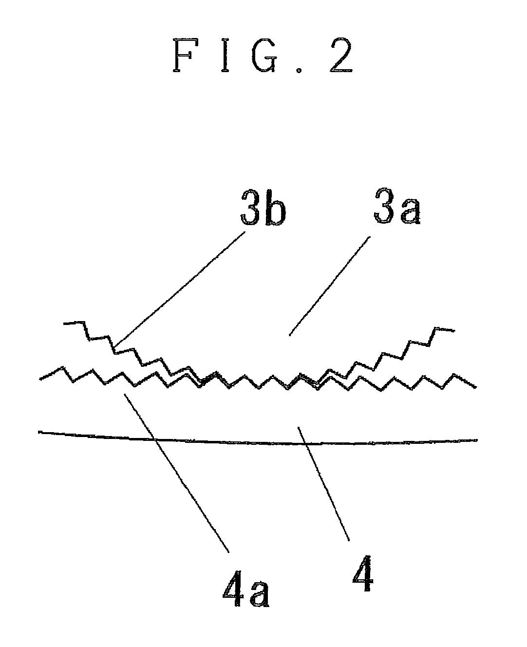
[0054]FIG. 2 is a detailed view of a contact portion between a stepped portion 3a of the roller and a decelerating plate 4 of an embodiment in the present invention and portions not shown in the figure are similar to those in FIG. 1 and not shown.

[0055]In the present embodiment, on contact faces of the pair of decelerating plates 4 with the stepped portions 3a and contact faces of the opposite stepped portions 3a with the decelerating plates 4, recessed and protruding teeth 3b and 4a to be engaged with each other are formed in a rotating direction of the rolling element.

[0056]A rotation axis of the roller is skewed with respect to a direction perpendicular to a transferring direction by a factor such as a nonuniform external load. Since a large skew angle has an adverse influence such as an increase in a frictional force, a supporting cage is conventionally used to control the skew. In the present embodiment, a revolution phase of the roller entering the contact point changing path ...

embodiment 3

[0058]FIGS. 3a to 3c show an embodiment of a barrel-shaped roller bearing of the present invention in which a contact point changing path a is provided to an inner ring. FIG. 3a is a sectional view along line X-X in FIG. 3b, FIG. 3b is a sectional view along line Y-Y in FIG. 3a, and FIG. 3c is a sectional view along line Z-Z in FIG. 3a. At a center of a barrel-shaped roller 3, an annular groove 3d having a rounded groove bottom face is formed. An outer ring 1 has a similar structure to that of the conventional art bearing. The inner ring 2 is divided into two at a center of a transfer groove 2a and an annular groove 2b is formed in a divided face. An annular decelerating plate 4 is mounted in the groove 2b by clearance fitting and a pin 5 driven in the inner ring restrains rotation of the decelerating plate 4.

[0059]An outer diameter of the decelerating plate 4 is slightly greater than a diameter of an inscribed circle at the groove bottom of the groove 3b of the roller in a state wh...


PUM

PropertyMeasurementUnit
radiusaaaaaaaaaa
radiusaaaaaaaaaa
radiusaaaaaaaaaa

Abstract

Intervals are provided between rolling elements in a load area to avoid jostling of rolling elements in a rolling device. A portion of a transfer groove has such a sectional shape as to form a contact point changing path for coming in contact with smaller diameter portions of the rolling elements than outer diameters of the rolling elements to thereby reduce revolution quantities of the rolling elements to bring rolling elements in contact with or close to each other at this portion. Then, when the rolling elements come out of the contact point changing path, the outer diameter portions of the rolling elements come in contact with the transfer groove to thereby increase the revolution quantities of the rolling elements to create intervals between the rolling elements entering the load area.

Description

BACKGROUND OF THE INVENTION[0001]1. Field of the Invention[0002]The present invention relates to an improvement of a rolling device.[0003]2. Description of the Related Art[0004]In a rolling device including a pair of transfer grooves and a plurality of rolling elements inserted between the transfer grooves, individual rolling elements rotate in the same direction, which means that rolling element surfaces adjacent to each other move in opposite directions. As a result, large sliding friction is caused by contact between the rolling elements, if the rolling device does not have a supporting cage.[0005]To ease this problem, it is a common practice to use a supporting cage for retaining the rolling elements at uniform intervals (see Patent Document 1, for example).[0006]Patent Document 1: Japanese Unexamined Patent Publication No. 2005-163997SUMMARY OF THE INVENTION[0007]However, even if the supporting cage in Patent Document 1 is used, sliding friction is still generated between rolli...

Claims


Application Information

Patent Timeline
Patent Type & Authority Patents(United States)
IPC IPC(8): F16C19/50F16C19/24
CPCF16C39/02F16C33/306F16C25/08F16C2240/40F16C33/36F16C23/086F16C29/0609Y10T29/49679F16C19/26
Inventor KAWASHIMA, SOSUKE
Owner COO SPACE CO LTD
Why Eureka
Try Eureka