
Sludge processing apparatus and method

a technology of sludge and processing equipment, which is applied in the direction of separation processes, filtration separation, grain husking, etc., can solve the problems that non-uniform sludge pieces are known to inhibit the effective removal of such a vacuuming

Inactive Publication Date: 2011-09-13
STAPLES WESLEY A
View PDF67 Cites 23 Cited by
  • Summary
  • Abstract
  • Description
  • Claims
  • Application Information

AI Technical Summary

Benefits of technology

[0009]A method aspect of the invention may comprise depositing material to be processed into the trough at a location generally between the upstream and downstream ends, operating the auger at a rotational speed and direction so as to force the material received within the trough upstream, continuing to operate the auger for forcing the material against an upstream end surface of the trough for a breaking up thereof, optionally adding fluid to the trough for diluting the material and enhancing a flow of the broken up material downstream under a force of gravity, allowing the diluted material flowing downstream to enter the chopper, chopping the diluted material to a desired consistency, and optionally pumping the chopped material to a desired location. Further, the method may comprise filtering the diluted material prior to the chopping. Yet further, the method may comprise positioning the hopper for receiving the material and depositing the material to be processed into the hopper for the depositing into the trough, and optionally cutting the material prior to depositing the material into the trough.

Problems solved by technology

However, non-uniform sludge pieces are known to inhibit the effective removal using such a vacuuming.

Method used


Image

  • Sludge processing apparatus and method
  • Sludge processing apparatus and method
  • Sludge processing apparatus and method

Examples


Embodiment Construction

[0017]The present invention will now be described more fully hereinafter with reference to the accompanying drawings, in which preferred embodiments of the invention are shown. This invention may, however, be embodied in many different forms and should not be construed as limited to the embodiments set forth herein. Rather, these embodiments are provided so that this disclosure will be thorough and complete, and will fully convey the scope of the invention to those skilled in the art.

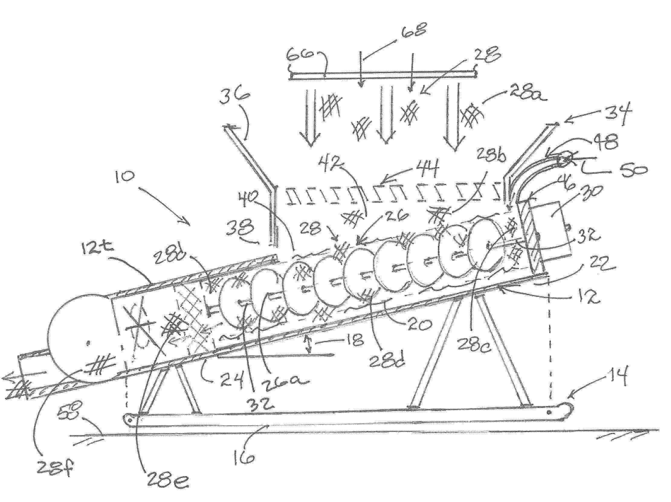
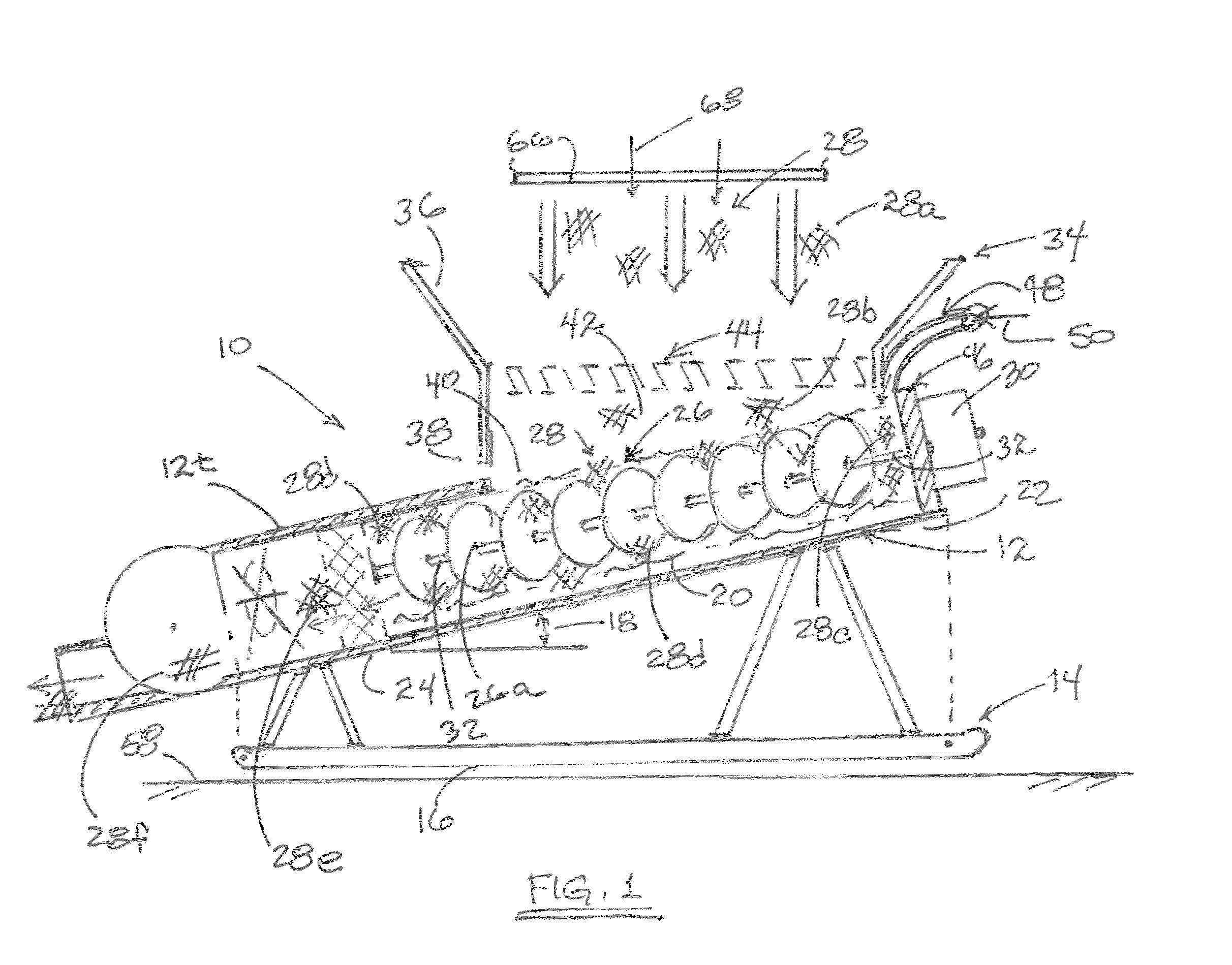
[0018]By way of example for embodiments of the invention, reference is initially made to FIG. 1 diagrammatically illustrating one sludge processing apparatus 10, a trough 12 carried by a skid 14, wherein the trough is inclined relative to a supporting surface 16 for the skid at an angle 18 sufficient for permitting fluid 20 to flow downstream from a first elevated end 22 of the trough to a second end 24 as a result of gravitational forces.

[0019]With continued reference to FIG. 1, an auger 26 is carried ...


PUM

PropertyMeasurementUnit
gravitational forcesaaaaaaaaaa
speedaaaaaaaaaa
sizeaaaaaaaaaa

Abstract

Material to be processed, such as sludge, is deposited into the trough having an auger operating at a rotational speed and direction so as to force the material received within the trough upstream against a rigid surface for breaking up the sludge. A cutting fluid is added to the trough for diluting the sludge and enhancing a flow of the broken up sludge downstream under a force of gravity, allowing the sludge to enter a chopper, where it is chopped to a desired consistency before being pumped to a desired location. The diluted sludge may be filtered prior to chopping. A hopper and cutter may be used to receive the unprocessed sludge for cutting prior to being deposited into the trough. As a result, sludge in ranges from soft to hard states is converted to a fluid form capable of being pumped.

Description

CROSS-REFERENCE TO RELATED APPLICATIONS[0001]This application claims the benefit of U.S. Utility patent application Ser. No. 11 / 345,607 having filing date of Feb. 1, 2006 for “Sludge Processing Apparatus and Method,” which itself claims the benefit of U.S. Provisional Application No. 60 / 649,049 having filing date of Feb. 1, 2005. the disclosures of which are hereby incorporated by reference herein in their entirety, and all commonly owned.FIELD OF THE INVENTION[0002]The present invention generally relates to the field of waste products removal, and in particular to an apparatus and method for removing solid and liquid waste products such as sludge from liquid storage tanks.BACKGROUND OF THE INVENTION[0003]In today's industrialized, high tech world, we have new products being developed on a regular basis. Large industrial complexes blend, burn, mix, settle, ionize, dispose and utilize various processes in an attempt to eliminate resulting waste products in a low cost controlled manne...

Claims


Application Information

Patent Timeline
Patent Type & Authority Patents(United States)
IPC IPC(8): B02C19/00
CPCB02C18/0092B02C19/22B02C23/02
Inventor STAPLES, WESLEY A.
Owner STAPLES WESLEY A
Features
  • Generate Ideas
  • Intellectual Property
  • Life Sciences
  • Materials
  • Tech Scout
  • Unparalleled Data Quality
  • Higher Quality Content
  • 60% Fewer Hallucinations
Learn More