Torque ripple mitigation controller with vibration sensor delay compensation

a technology of vibration sensor and torque ripple, applied in the direction of motor/generator/converter stopper, dynamo-electric converter control, instruments, etc., can solve the problems of limiting the applicability of low-volume (custom) applications to torque ripple created by permanent magnet synchronous machines (pmsm), and neither the position observer nor the torque ripple mitigation control were demonstrated in hardware. to achieve the effect of reducing costs

Active Publication Date: 2011-09-13
PURDUE RES FOUND INC
View PDF9 Cites 25 Cited by
  • Summary
  • Abstract
  • Description
  • Claims
  • Application Information

AI Technical Summary

Benefits of technology

[0011]The overall torque ripple mitigation strategy using an embodiment of the Hall-effect-based position observer has been validated in simulation and hardware using a 3-phase, 12-pole, 1 slot/pole/phase machine with a non-sinusoidal back-emf. Prior to mitigation, the torque ripple resulting from cogging and stator/rotor field interaction is on the order of 1-2 Nm (compa

Problems solved by technology

Torque ripple created by permanent magnet synchronous machines (PMSM) is an issue in numerous applications.
This limits their applicability to low-volume (custom) applications.
Despite their promise, a barrier to widespread use of these and

Method used


Image

  • Torque ripple mitigation controller with vibration sensor delay compensation
  • Torque ripple mitigation controller with vibration sensor delay compensation
  • Torque ripple mitigation controller with vibration sensor delay compensation

Examples


Embodiment Construction

[0030]For the purpose of promoting an understanding of the principles of the invention, reference will now be made to the embodiments illustrated in the drawings and specific language will be used to describe the same. It will nevertheless be understood that no limitation of the scope of the invention is thereby intended, such alterations and further modifications in the illustrated device and such further applications of the principles of the invention as illustrated therein being contemplated as would normally occur to one skilled in the art to which the invention relates.

I. Measurement and Mitigation of Torque Ripple Induced Vibration

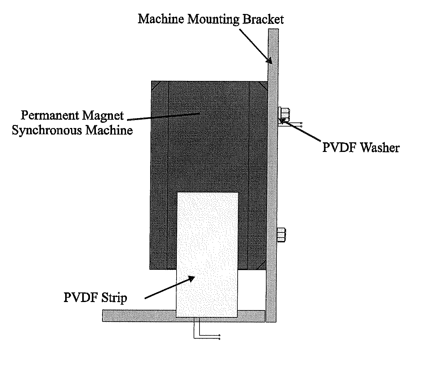
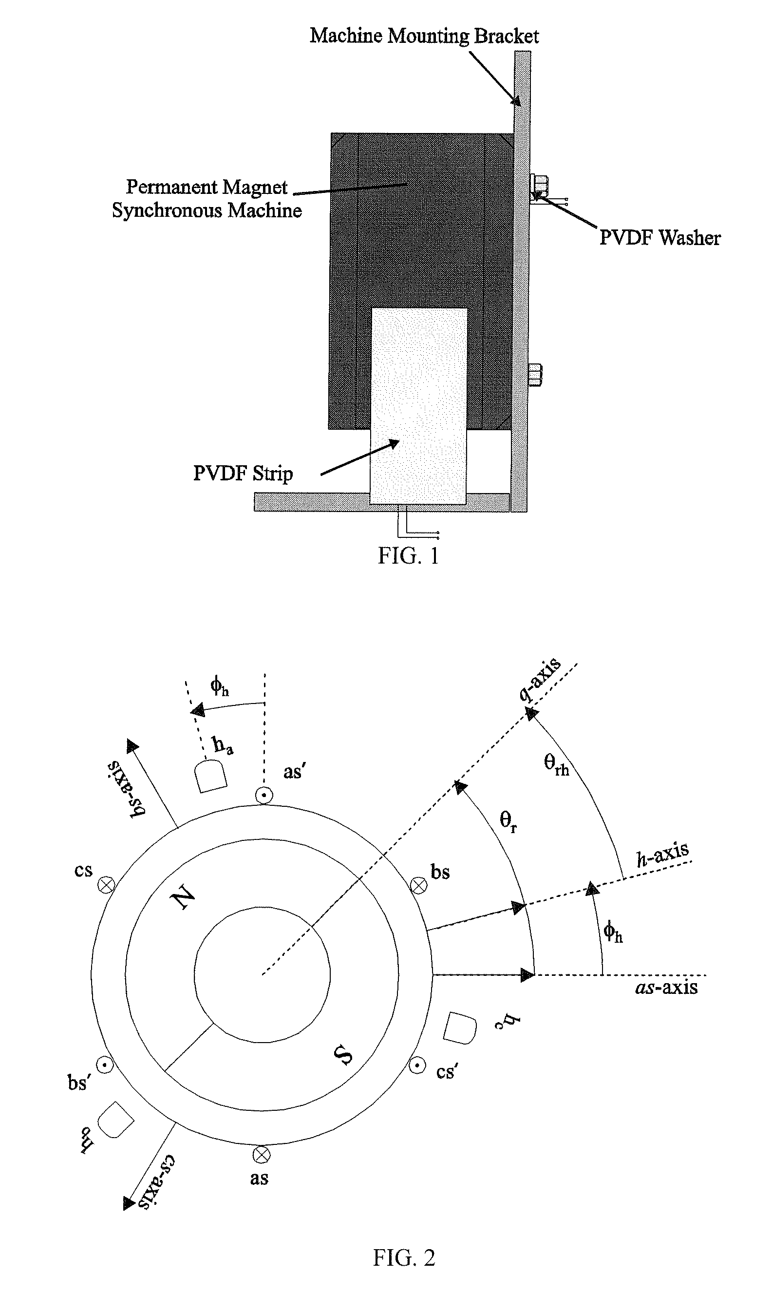
[0031]The techniques disclosed herein are demonstrated using the torque ripple mitigation strategy proposed in [26]. Within the strategy, a piezoelectric polyvinylidene fluoride (PVDF) polymer film is used as a sensor to detect torque-ripple-induced vibration. A diagram of possible sensor arrangements is shown in FIG. 1. In [26], the sensor was creat...


PUM


Abstract

An enhanced torque ripple mitigation algorithm for permanent magnet synchronous machines (PMSMs), the algorithm including compensation for sensor delay.

Description

CROSS-REFERENCE TO RELATED APPLICATIONS[0001]This application claims the benefit of U.S. Provisional Patent Application No. 60 / 868,990, filed Dec. 7, 2006, and Application No. 60 / 869,140, filed Dec. 8, 2006.GOVERNMENT RIGHTS[0002]This invention was made with government support under N00024-02-C-4056 with the Naval Sea Systems Command. The government has certain rights in the invention.BACKGROUND OF THE INVENTION[0003]This invention relates to electric motor controls, and more particularly to devices and methods for mitigation of torque ripple in an electric motor.[0004]Torque ripple created by permanent magnet synchronous machines (PMSM) is an issue in numerous applications. Traditionally, approaches to mitigate torque ripple have focused upon one of two methods. In the first, mitigation is achieved through machine design (i.e. adjusting magnet / tooth / slot geometry, etc). In the second, harmonics of stator current are controlled to minimize torque ripple. The focus of the research pr...

Claims


Application Information

Patent Timeline
IPC IPC(8): G05B5/01
CPCH02P6/16H02P21/05H02P21/13H02P23/04H02P23/12H02P29/0038H02P29/50
Inventor PEKAREK, STEVEN D.BECCUE, PHILIP B.
Owner PURDUE RES FOUND INC
Why Eureka
Try Eureka