
Hearing aid with feedback model gain estimation

a feedback model and hearing aid technology, applied in the field of hearing aids, can solve the problems of unstable once-inaudible acoustic feedback becoming audible, and the output of hearing aids can exceed the attenuation offered by ear moulds/shells, etc., to increase the stability margin, increase the stability of hearing aids, and increase processor gains

Active Publication Date: 2011-09-13
WIDEX AS
View PDF3 Cites 13 Cited by
  • Summary
  • Abstract
  • Description
  • Claims
  • Application Information

AI Technical Summary

Benefits of technology

[0017]Preferably, the model gain is continuously determined in order to cope with different fluctuating acoustic environmental surroundings and at the same time to allow maximum desired processor gain in the hearing aid, so that a time varying processor gain constraint imposed is safe without being overly restrictive.
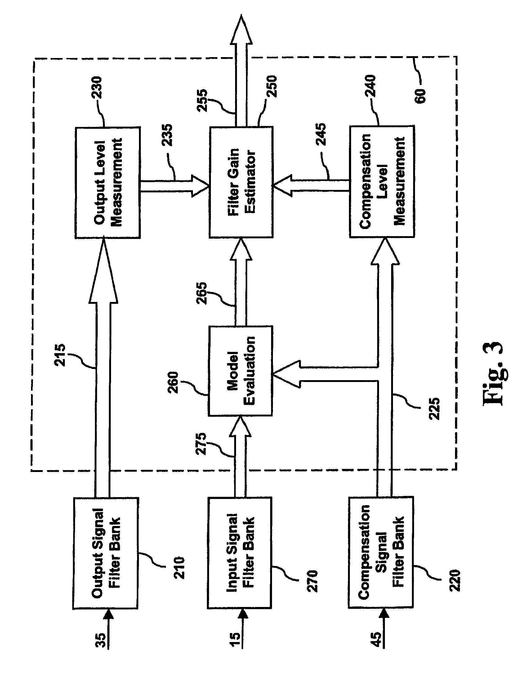
[0021]According to a preferred embodiment of the present invention, spectral signal path gains of the processor are adjusted in accordance with respective time varying upper gain limits. These spectral upper gain limits are obtained by measuring the spectral acoustic feedback gains in the adaptive feedback suppression filter. Spectral gains are necessary when the signal paths of the respective signals in the hearing aid are split into two or more frequency bands. For example, the electrical input signal is split into different frequency bands before being inputted to the processor, implying that the processor has to estimate two or more spectral gains according to the frequency bands of the electrical input signal. In that case it is also necessary to differentiate the model gain estimate into an equal number of frequency bands in order to derive upper gain limits for each frequency band. Normally, the processor is preceded by, e.g., an FFT-circuit or an input signal filter bank splitting the electrical input signal into respective frequency bands. It is therefore possible to calculate the spectral acoustic feedback gains with exactly the same bandwidth by the processor in the signal path by using the same filter bank or FFT-circuit and thereby reducing the error of the estimate.
[0028]The result of adjusting the spectral signal path gain or gains by means of time varying feedback model gain estimates is to increase the stability of the hearing aid. In case the adaptive feedback suppression filter (also referred to as the model) produces a feedback cancellation signal that corresponds to or is at least close to the acoustic feedback signal, the model has converged correctly and the feedback component of the electrical input signal will be reduced, thereby increasing the stability margins in all frequency bands. As a result, larger processor gains are possible. At the same time, the model gain estimates will become more accurate. This means, that upper gain limits can be less restrictive, and it is possible to increase these with some amounts, depending on the accuracy of the model. However, it is advisable to select the upper gain somewhat lower than required to achieve stability, because gains close to the upper limit can result in unpleasant audible effects.

Problems solved by technology

But when in-situ gain of the hearing aid is sufficiently high, or when a larger than optimal size vent is used, the output of the hearing aid generated within the ear canal can exceed the attenuation offered by the ear mould / shell.
The output of the hearing aid then becomes unstable and the once-inaudible acoustic feedback becomes audible, e.g. in the form of ringing, whistling noise or howling.
For many users and the people around, such audible acoustic feedback is an annoyance and even an embarrassment.
Feedback also distorts signal processing and limits the gain available for the user.
Audible feedback is a sign of instability of the hearing instrument system.
Managing feedback by gain reduction is in particular a problem in linear hearing aids.
Unfortunately, the typical feedback path also provides less attenuation at high frequencies than at low frequencies.
Therefore, the risk of audible feedback is highest in the higher frequency range.
However, gain in the higher frequency regions is also compromised with this approach.
Speech intelligibility may suffer as a consequence.
An additional problem with managing feedback in linear hearing aids is that these devices provide the same gain at all input levels, so that a gain constraint that is imposed to combat feedback will be effective at all input levels.
However, it is not possible to directly measure or monitor the loop gain in a hearing aid by means of a feedback suppression filter.
However, such methods for determining allowable processor gain are expensive in hardware and it is also necessary to have access to the current coefficients of the feedback suppression filter.

Method used


Image

  • Hearing aid with feedback model gain estimation
  • Hearing aid with feedback model gain estimation
  • Hearing aid with feedback model gain estimation

Examples


first embodiment

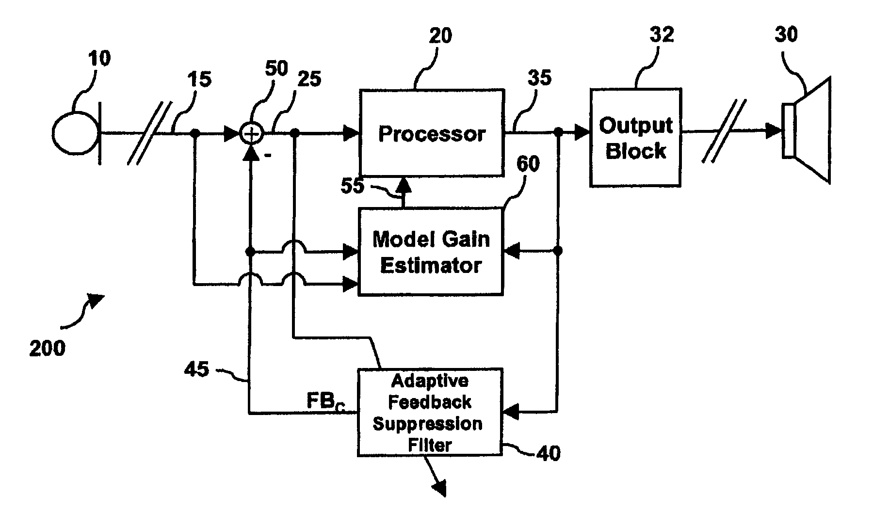
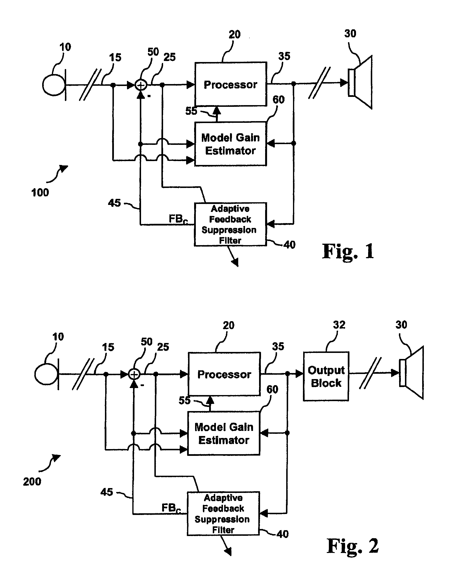
[0046]Reference is now made to FIG. 1, which shows a block diagram of a hearing aid according to the present invention.

[0047]The signal path of the hearing aid 100 comprises an input transducer or microphone 10 transforming an acoustic input signal into an electrical input signal 15 by, e.g., converting the sound signal to an analogue electrical signal, an A / D-converter (not shown) for sampling and digitising the analogue electrical signal into a digital electrical signal, and an input signal filter bank (not shown in FIG. 1) for splitting the input signal into a plurality of frequency bands. The signal path further comprises a processor 20 for generating an amplified electrical output signal 35 and an output transducer (loud speaker, receiver) 30 for transforming the electrical output signal into an acoustic output signal. The amplification characteristic of the processor 20 may be non-linear, e.g. it may show compression characteristics as it is well-known in the art, providing mo...


PUM


Abstract

A hearing aid includes an input transducer for transforming an acoustic input signal into an electrical input signal, a processor for generating an electrical output signal by amplifying the electrical input signal with a processor gain, an output transducer for transforming the electrical output signal into an acoustic output signal, an adaptive feedback suppression filter for generating a feedback cancellation signal, and a model gain estimator generating an upper processor gain limit and for providing a control parameter indicating a possible misadjustment of the model.

Description

RELATED APPLICATIONS[0001]The present application is a continuation-in-part of International application No. PCT / EP2004 / 053547, filed on Dec. 16, 2004, with The European Patent Office and published as WO 2006 / 063624 A1.BACKGROUND OF THE INVENTION[0002]1. Field of the Invention[0003]The invention relates to the field of hearing aids. More specifically, the invention relates to a hearing aid with an adaptive filter for suppression of acoustic feedback. The invention also relates to a method of adjusting the signal path gain and to an electronic circuit for a hearing aid. The invention further relates to a hearing aid having means for measuring the spectral gain in an adaptive feedback suppression filter, to a method of measuring the spectral gain in the adaptive feedback suppression filter, and to an electronic circuit for such a hearing aid.[0004]2. The Prior Art[0005]Acoustic feedback occurs in all hearing instruments when sounds leak from the vent or seal between the ear mould and ...

Claims


Application Information

Patent Timeline
Patent Type & Authority Patents(United States)
IPC IPC(8): H04R25/00
CPCH04R25/453
Inventor KLINKBY, KRISTIAN TJALFEFOEH, HELGE PONTOPPIDANTHIEDE, THILO VOLKER
Owner WIDEX AS
Learn More