Optical packet switching apparatus and method therefor

a technology of optical packet switching and control signals, applied in data switching networks, multiplex communication, digital transmission, etc., can solve the problems of deteriorating transfer efficiency, and the inability of technology to suppress the skew among switch control signals, and achieve the effect of suppressing the skew and suppressing the skew

Inactive Publication Date: 2011-09-13
FUJITSU LTD
View PDF5 Cites 2 Cited by
  • Summary
  • Abstract
  • Description
  • Claims
  • Application Information

AI Technical Summary

Benefits of technology

[0015]The present invention was made in view of the situations above, and the object of the present invention is to provide an optical packet switching apparatus including a technology that suppresses the skew among multiple switch control signals that switch the ON / OFF states of multiple optical switches and an optical switch control method that suppresses the skew among multiple switch control signals that switch the ON / OFF states of multiple optical switches and switches multiple optical switches with multiple switch control signals with the suppressed skew.
[0020]the control section adjusts the transmission times of the multiple switch control signals such that the difference in delay time measured by the delay measuring means can be cancelled and the multiple switch control signals transmitted through the multiple signal transmission lines can arrive at the multiple optical switches simultaneously and transmits the multiple switch control signals.
[0021]The optical packet switching apparatus of the present invention has the delay measuring means and measures a difference in delay time of signal transmission within multiple signal transmission lines by the delay measuring means. Then, in a stage for actually controlling the ON / OFF states of the optical switches, the transmission times of the multiple switch control signals are adjusted such that the multiple switch control signals to be transmitted through the multiple signal transmission lines can arrive at the multiple optical switches simultaneously, and the multiple switch control signals are transmitted. Thus, the skew among the multiple switch control signals can be suppressed, and the path of an optical packet can be switched at an accurate time.
[0024]Under this configuration, the difference in delay time of signal transmission among multiple signal transmission lines can be calculated easily.
[0027]a control signal transmitting step of adjusting the transmission times of the multiple switch control signals such that the difference in delay time measured by the delay measuring step can be cancelled and the multiple switch control signals transmitted through the multiple signal transmission lines can arrive at the multiple switches simultaneously and transmitting the multiple switch control signals.

Problems solved by technology

When a skew occurs among multiple switch control signals having arrived at the multiple optical switches, a waiting time occurs among the packets, which causes the deterioration of the transfer efficiency, since no proper buffer element (delay element) exist that can hold an optical signal for a while as it is in a case where switching is performed with the optical signal as it is.
Japanese Laid-open Patent Publication No. 2001-53684 discloses a technology that controls the drift of an optical signal, but the technology cannot suppress the skew among switch control signals.

Method used


Image

  • Optical packet switching apparatus and method therefor
  • Optical packet switching apparatus and method therefor
  • Optical packet switching apparatus and method therefor

Examples


first embodiment

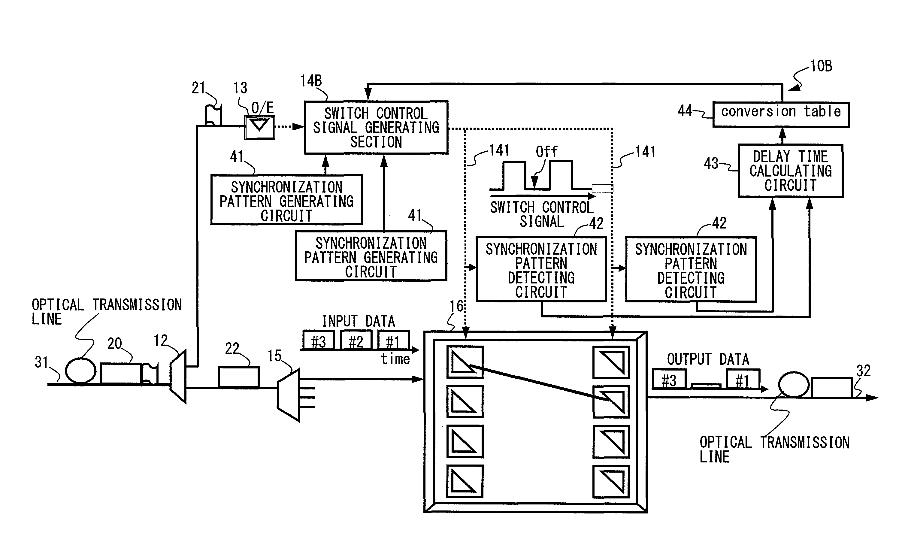
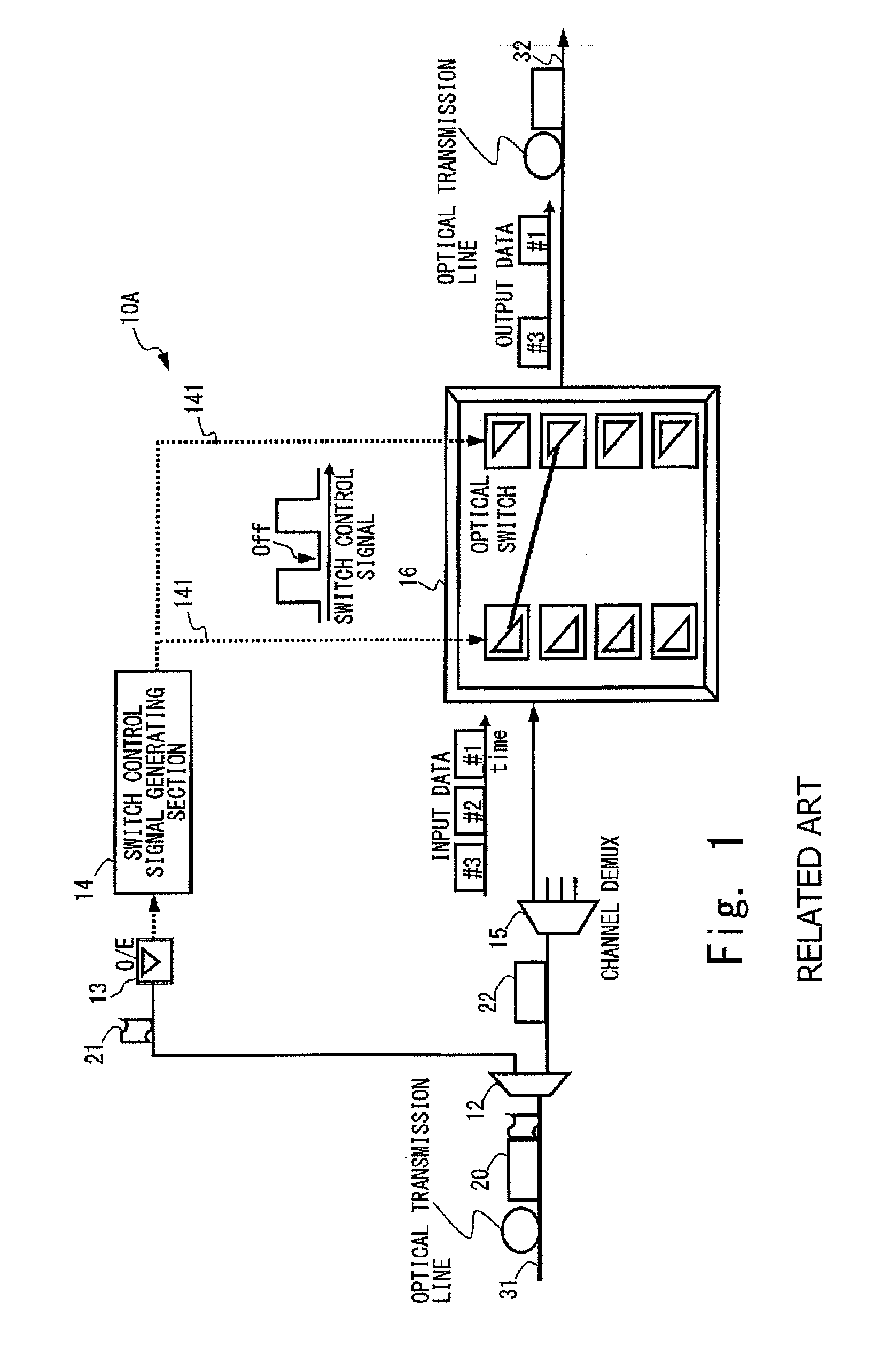
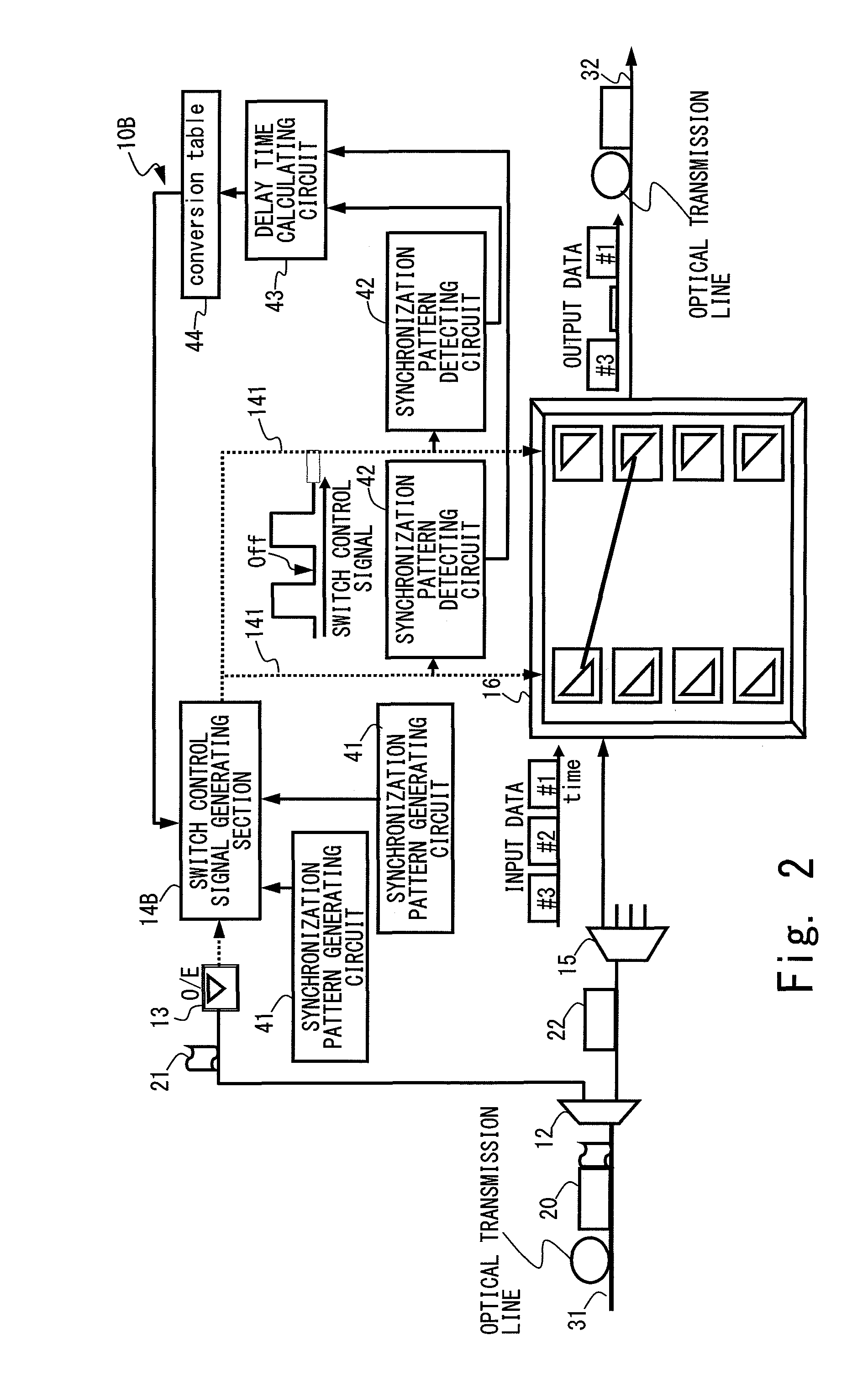
[0038]FIG. 2 is a schematic configuration diagram of an optical packet switching apparatus as the present invention. In FIG. 2, the same reference numerals as the reference numerals given in FIG. 1 are given to the same components as the components of the optical packet switching apparatus 10A shown in FIG. 1, and differences will be described.

[0039]In comparison with the optical packet switching apparatus 10A in FIG. 1, multiple synchronization pattern generating circuits 41, multiple synchronization pattern detecting circuits 42, a delay time calculating circuit 43, and a conversion table 44 are deployed in an optical packet switching apparatus 10B shown in FIG. 2. Before using the optical packet switching apparatus 10B actually, the synchronization pattern generating circuits 41 generate a synchronization pattern signal for detecting the delay of the signals on signal transmission lines 141, transmit the synchronization pattern signal to a switch control signal generating section...

second embodiment

[0041]FIG. 3 is a schematic configuration diagram of an optical packet switching apparatus as the present invention.

[0042]In comparison with the optical packet switching apparatus 10B of the first embodiment shown in FIG. 2, an optical packet switching apparatus 10C of the second embodiment shown in FIG. 3 is a more specifically illustrated embodiment. The optical packet switching apparatus 10C shown in FIG. 3 includes the optical switch section 16 having two input ports 16-1a and 16-1b and two output ports 16-2a and 16-2b.

[0043]FIG. 4 is a schematic configuration diagram of the optical switch section 16 included in the optical packet switching apparatus 10C shown in FIG. 3. Now, before entirely describing the optical packet switching apparatus 10C in FIG. 3, the configuration of the optical switch section 16 shown in FIG. 4 will be described.

[0044]The optical switch section 16 shown in FIG. 4 includes two input ports 16-1a and 16-1b, two photocouplers 162-1 and 162-2, four upstrea...


PUM


Abstract

An optical switch section that switches the path of an optical packet transmitted thereto and outputs the optical packet, and a control section that generates multiple switch control signals in accordance with the destination of an optical packet transmitted thereto, transmits the multiple control signals to the optical switch section through multiple signal transmission lines and controls the ON / OFF states of multiple optical switches are included, and delay measuring means for measuring a difference in delay time among the multiple signal transmission lines is provided. In this case, the control section adjusts the transmission times of the multiple switch control signals such that the difference in delay time measured by the delay measuring means can be cancelled and that the multiple switch control signals transmitted through the multiple signal transmission lines can arrive at the multiple optical switches simultaneously and transmits the multiple switch control signals.

Description

BACKGROUND OF THE INVENTION[0001]1. Field of the Invention[0002]The present invention relates to an optical packet switching apparatus that switches the path of an optical packet transmitted thereto to the destination of the optical packet and transmits the optical packet and an optical switch control method that controls the ON / OFF states of an optical switch included in the optical packet switching apparatus.[0003]2. Description of the Related Art[0004]For avoiding the bottlenecks (limits in band and amount of signal) of electric wiring technologies in signal switching within a high-speed router, the application of an optical packet switch using a wide band characteristic of an optical transmission technology has been studied and has been partially implemented until now. An optical signal is once converted to an electric signal for switching in an optical packet switching system having been adopted until now, and the scale of the switching has been largely extended with the increa...

Claims


Application Information

Patent Timeline
Patent Type & Authority Patents(United States)
IPC IPC(8): H04J14/00H04B10/27H04B10/07H04L12/931
CPCH04Q11/0005H04Q11/0066H04Q2011/0039H04Q2011/0045
Inventor MATSUNAGA, KOJIKAI, YUTAKA
Owner FUJITSU LTD
Why Eureka
Try Eureka