Inverter for grounded direct current source, more specifically for a photovoltaic generator

a direct current source and photovoltaic generator technology, applied in the direction of electric variable regulation, process and machine control, instruments, etc., can solve the problems of not being able to directly ground the solar generator, the capacitive leakage current can only be minimized but not completely avoided, and the switch loss is low, so as to achieve the effect of low cost, low cost and low load

Inactive Publication Date: 2011-09-20
SMA SOLAR TECH AG
View PDF16 Cites 6 Cited by
  • Summary
  • Abstract
  • Description
  • Claims
  • Application Information

AI Technical Summary

Benefits of technology

[0017]The object of the invention is to provide an inverter by means of which capacitive leakage currents are prevented at little expense in terms of wiring and that allows for little load on the switches.
[0019]The invention allows for a circuit array with high efficiency thanks to minimum switching losses in the DC-DC converter. The DC generator is allowed to have a fix potential with respect to ground. Moreover, it is possible to feed a continuous current into the utility grid. Additionally, any grounding of the photovoltaic generator can be achieved. HF leakage currents of the photovoltaic generator or of another direct voltage generator are avoided. The invention further allows for high efficiency also in part load range as well as a small size for the energy stores in the DC-DC converter because a potentially high switching frequency.
[0022]An advantage of the DC-DC converter utilized in accordance with the invention is that, in particular thanks to a series resonance oscillating circuit with divided oscillating circuit capacitor, the participating switches are relieved to a large extent from switching losses on the one side and two voltage intermediate circuits which are charged on two poles with respect to ground are supplied sufficiently symmetrically on the other side. As a result, current can be fed into a one-phase grid related to earth or into a 3-phase grid with earthed neutral thanks to a pulse inverter connected downstream thereof. Thanks to the particular topology of the circuit, the photovoltaic generator side and the grid side are separated in terms of direct current. This galvanic isolation is achieved by preferably two or even more oscillating circuit capacitors. Since these capacitors absorb the DC difference voltage between the photovoltaic generator side and the constituent parts of the direct voltage intermediate circuit of the inverter, it is possible to ground the photovoltaic generator both with its negative terminal and with its positive terminal.
[0023]In accordance with the invention, there is provided that the oscillating circuit inverter is configured to be a series-compensated oscillating circuit inverter with a choke and a capacitor arrangement connected in series. By applying the principle of a series compensated oscillating circuit inverter, the switch-off losses of the active switches are almost completely eliminated. Depending on the control method, the switch-on losses of these switches and the commutation losses of the diodes can also be avoided in practice. For this purpose, one allows the current to be intermittent or to only overlap slightly so that the current steepness is limited by the very oscillating circuit during switching. In this way, switch-on losses are avoided to a large extent and switch-off losses of active switches, almost completely.
[0025]The efficiency can be further improved by bridging the secondary active rectifier diode in its conducting phase with an also conductive FET.

Problems solved by technology

Through the low number of switches, switch losses are low but since the circuit needs absolutely symmetrical component parts such as chokes and capacitors, which is difficult in practical use, capacitive leakage currents can only be minimized but not completely avoided.
Another disadvantage is that it is not possible to directly ground the solar generator.
It is not possible to ground the generator with this circuit.
Direct grounding of the generator is also not possible.
Accordingly, between two switching processes and through asymmetries during switching, voltage differences form, which result in capacitive leakage currents.
One disadvantage is that the switches used are very much stressed because of the circuit array needed.
The disadvantage of this circuit is that the solar generator voltage is coupled directly to the intermediate circuit voltage.
Moreover, hard switching and intermediate magnetic storage of energy lead to high losses and large-sized passive components.
The use of only one switch for the two dual boost converters forcibly leads to higher load of said switch during switching operation.
This negatively affects both the robustness and the efficiency of this connection to a considerable extent.
The disadvantage of this circuit is that intermittent current pulses are impressed upon the grid, said pulses requiring a capacitive grid filter which, as a matter of principle, degrades not only the power factor but also the efficiency of the circuit in the part load range due to its own idle power need.
Moreover, with this circuit, the efficiency is adversely affected due to the great number of components participating concurrently in series in the current flow.
As a result, all the parts of the solar generator have a fix potential and capacitive leakage currents cannot flow in principle.
The disadvantage of these circuit proposals are the high voltage differences in the solar generator and at the switches as well as the additional losses in the compensation circuit and the at least four switches clocked at high frequency.
Another problem that has not been solved yet is that photovoltaic generators degrade very differently, depending on which pole they are grounded and on which technology was used for making them.

Method used


Image

  • Inverter for grounded direct current source, more specifically for a photovoltaic generator
  • Inverter for grounded direct current source, more specifically for a photovoltaic generator
  • Inverter for grounded direct current source, more specifically for a photovoltaic generator

Examples


Embodiment Construction

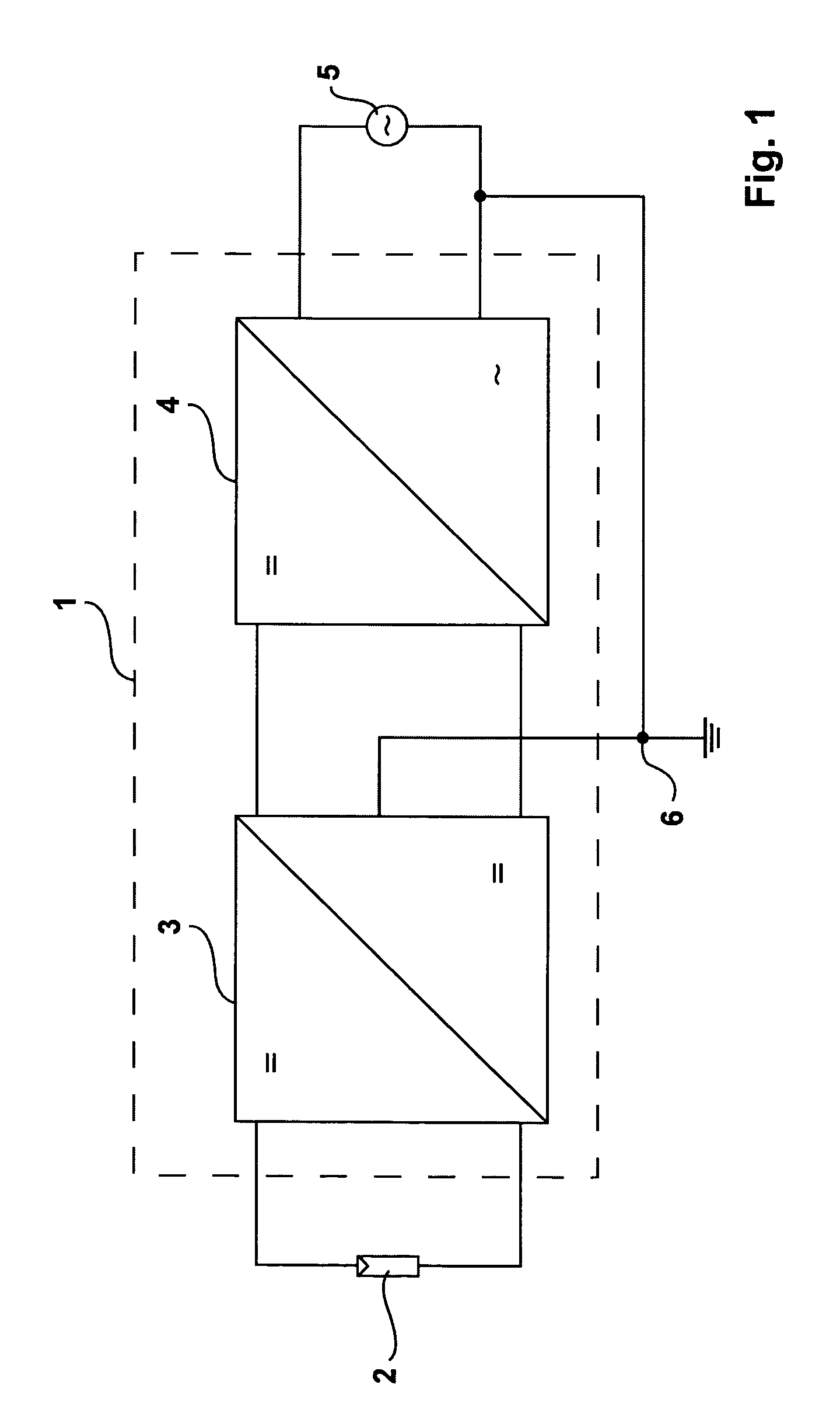
[0036]FIG. 1 shows a schematic diagram of the inverter 1 of the invention. A DC-DC converter 3 is connected downstream of a DC source, which is shown in FIG. 1 in the form of a photovoltaic generator 2. This DC-DC converter 3 supplies a DC-AC converter 4 the output of which is connected to a utility grid 5 and serves for feeding into said utility grid 5. The DC-DC converter 3 is thereby configured so as to allow for grounding both the DC source 2 and the grid 5 to a grounding point 6.

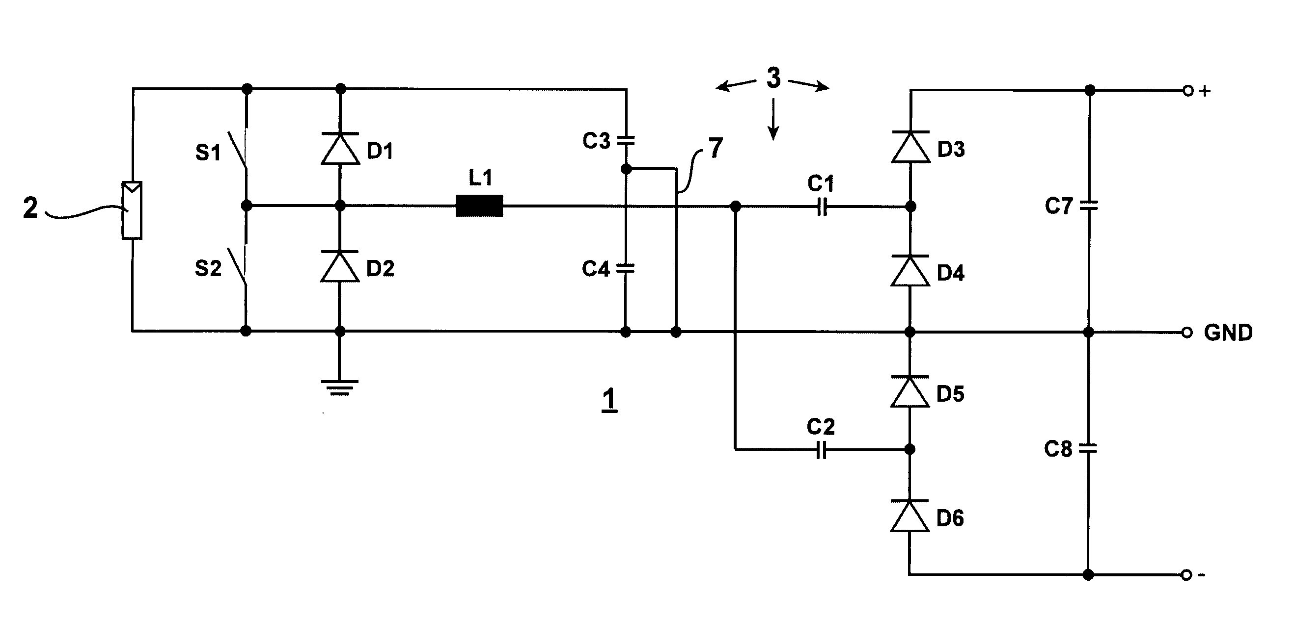
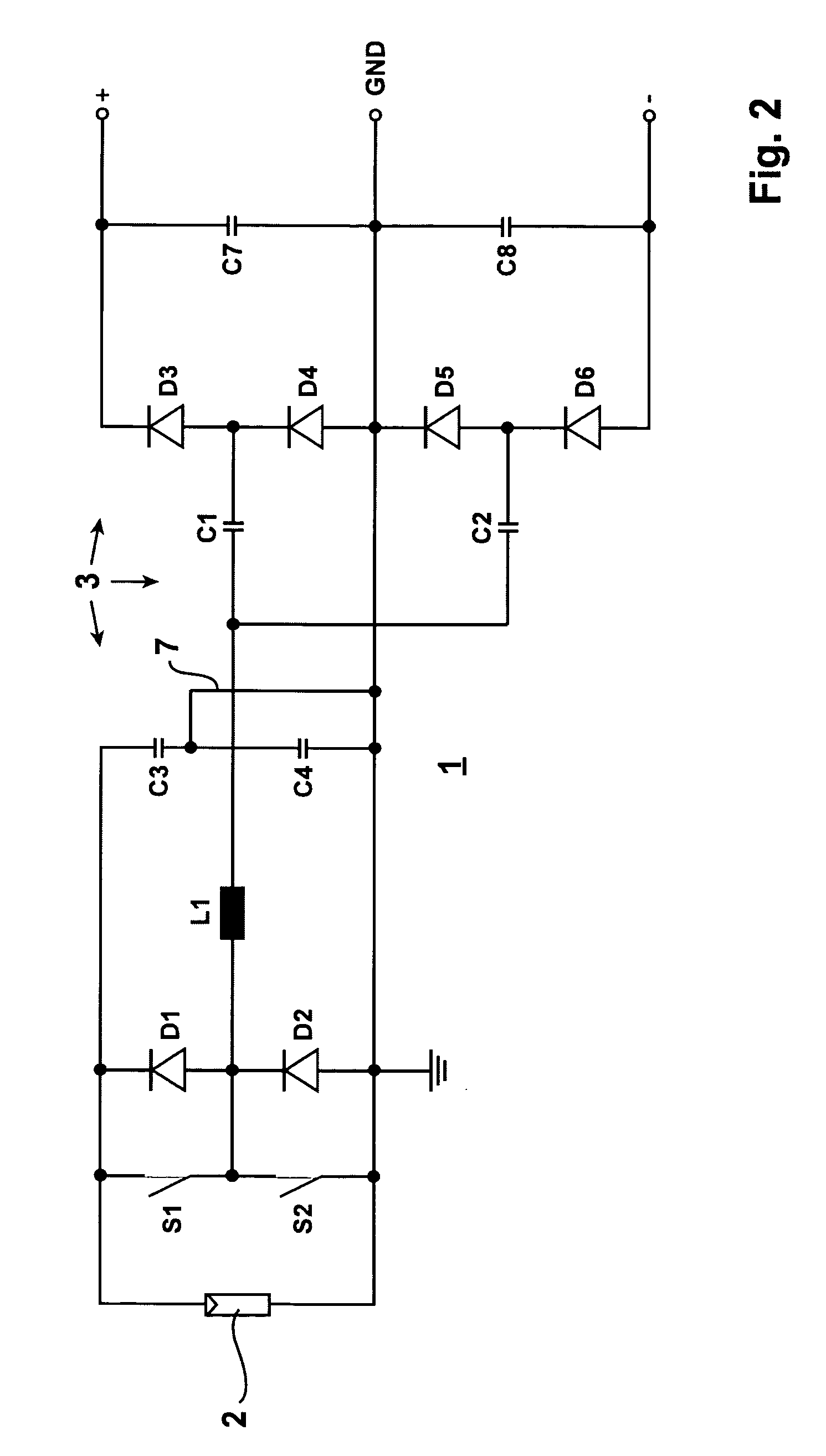
[0037]FIG. 2 shows a DC-DC converter 3 of the inverter 1 of the invention, which consists of the switches S1 and S2 with the respective anti-parallel diodes D1 and D2 which are switched on alternately, with the oscillating circuit inductivity L1, which can be implemented as a concentrated component part or as an assembled component part, with the two prorated oscillating circuit capacitors C1 and C2 as well as with the two rectifier branches. Each rectifier branch consists of two diodes. The first recti...


PUM


Abstract

An inverter (1) for a grounded direct voltage source, in particular for a photovoltaic generator (2), a battery or a fuel cell, for converting the direct voltage into an alternative voltage with a DC-DC converter (3) and a pulse inverter that is supplied by said DC-DC converter (3), said DC-DC converter (3) being configured to be an oscillating circuit inverter and comprising a series resonant oscillating circuit, said DC-DC converter (3), which is configured to be an oscillating circuit inverter, being configured to be a series-compensated oscillating circuit inverter with a choke (L1) and a series-mounted capacitor array consisting of two or several oscillating circuit capacitors, a rectifier bridge branch including 2 diodes (D3, D4; D5, D6, . . . ), being connected to each of the partial oscillating circuit capacitors, said rectifier bridge branch being connected with its positive or its negative pole to output side intermediate circuit capacitors which are preferably connected in series so that said DC-DC converter (3) delivers at least two bipolar output voltages and is combined with the pulse inverter (4) with a divided voltage intermediate circuit that is supplied from the oscillating circuit inverter.

Description

CROSS-REFERENCE TO RELATED APPLICATIONS[0001]This application claims Priority from German Application No. EP 07015324.2 filed on 4 Aug. 2007FIELD OF THE INVENTION[0002]The invention relates to an inverter for a grounded direct voltage source, in particular for a photovoltaic generator, a battery or a fuel cell, for converting the direct voltage into an alternating voltage with a DC-DC converter and a pulse inverter supplied by the DC-DC converter.[0003]Unavoidable parasitic capacitances occur on photovoltaic generators. If high-frequency clocked pulse inverters are being utilized for converting the generator's direct current into an alternating voltage at mains frequency, considerable, in parts not tolerable AC leakage currents can flow to ground from the photovoltaic generator.[0004]Great potential jumps at mains frequency can also lead to AC leakage currents because of their steep increase in voltage.DESCRIPTION OF THE PRIOR ART[0005]From the document DE 10 2004 037 446 A1 a trans...

Claims


Application Information

Patent Timeline
Patent Type & Authority Patents(United States)
IPC IPC(8): H02M3/335
CPCH02M3/158H02J3/383H02M2001/007H02M2001/009Y02B70/1425Y02E10/563H02J2300/24H02J3/381Y02B70/10Y02E10/56H02M1/009H02M1/007H02M7/05H02M7/48H02J7/35
Inventor ENGEL, BERNDMALLWITZ, REGINEZACHARIAS, PETER
Owner SMA SOLAR TECH AG
Why Eureka
Try Eureka