Plenum/plug fan assembly

a technology of plenum and fan assembly, which is applied in the direction of machines/engines, stators, liquid fuel engines, etc., can solve the problems of increasing lowering the static efficiency of the fan, so as to reduce the noise, increase the power input of the fan, and reduce the static efficiency

Active Publication Date: 2011-09-27
TWIN CITY FAN CO LTD
View PDF12 Cites 13 Cited by
  • Summary
  • Abstract
  • Description
  • Claims
  • Application Information

AI Technical Summary

Benefits of technology

[0012]In a further embodiment, a specially configured front (shroud) diffuser element, e.g., ring, is utilized, more generally, a structure which slows the air discharge velocity from the fan wheel / fan unit, is provided. In yet a further embodiment, an inlet diffuser is provide to selectively guide air flow into the fan wheel, preferably, but not necessarily, the inlet diffuser incorporates a blade pass frequency (BPF) tuned resonator. More specific features and advantages obtained in view of those features will become apparent with reference to the drawing figures and DETAILED DESCRIPTION OF THE INVENTION.

Problems solved by technology

Fan silencers have traditionally achieved noise reduction at the expense of a static pressure drop resulting in an increase in power input to the fan, and consequently lowering its static efficiency.

Method used


Image

  • Plenum/plug fan assembly
  • Plenum/plug fan assembly
  • Plenum/plug fan assembly

Examples


Embodiment Construction

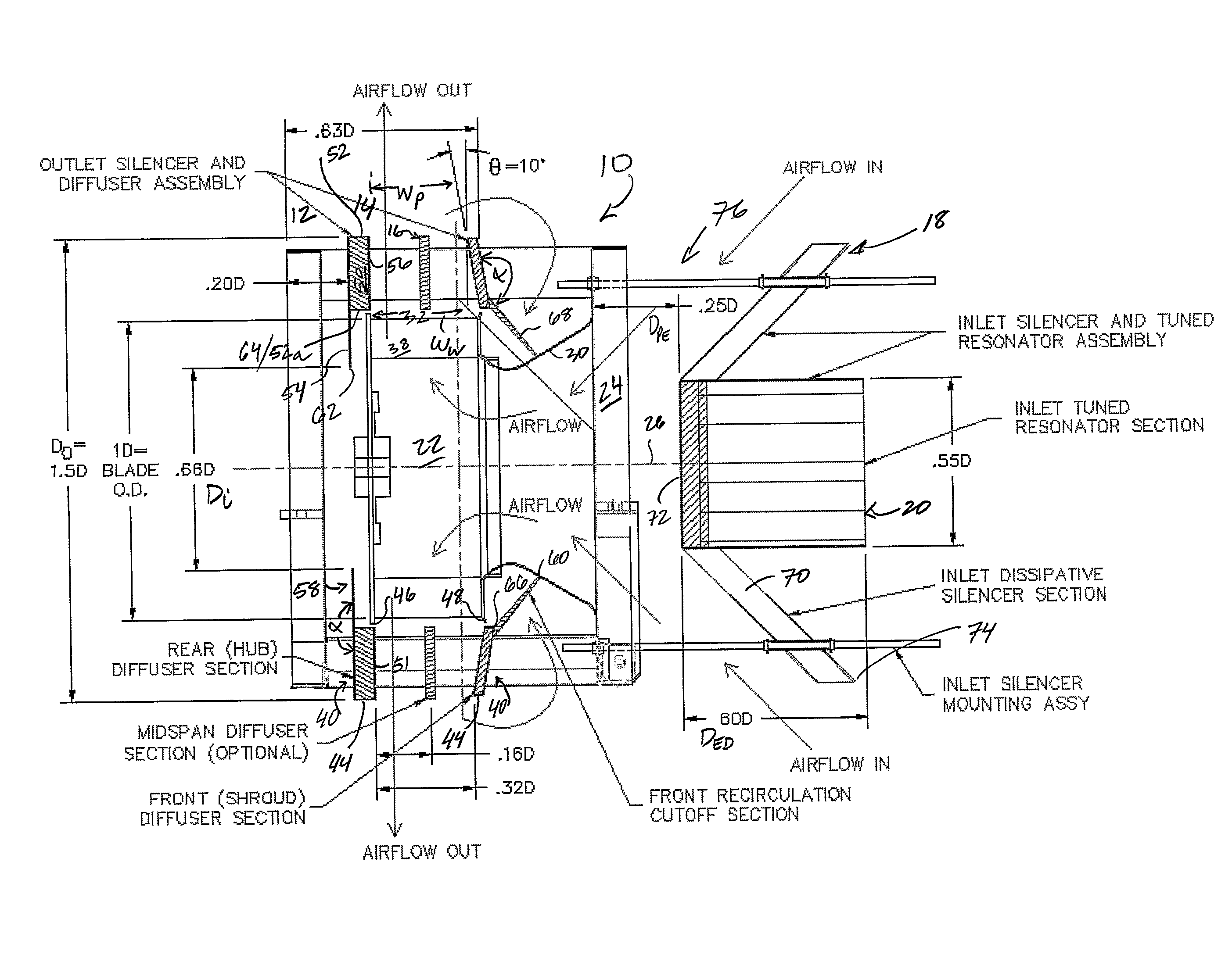
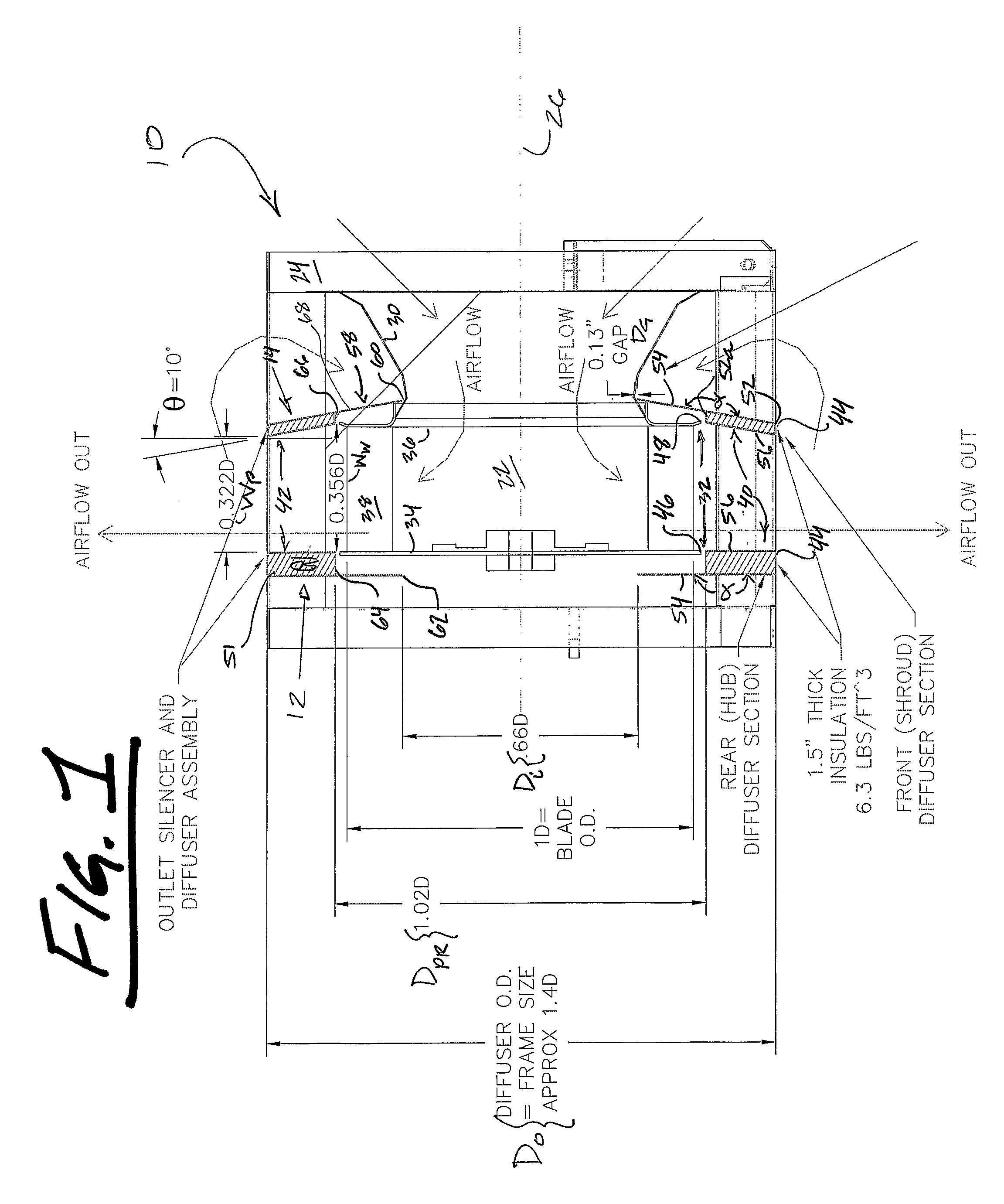
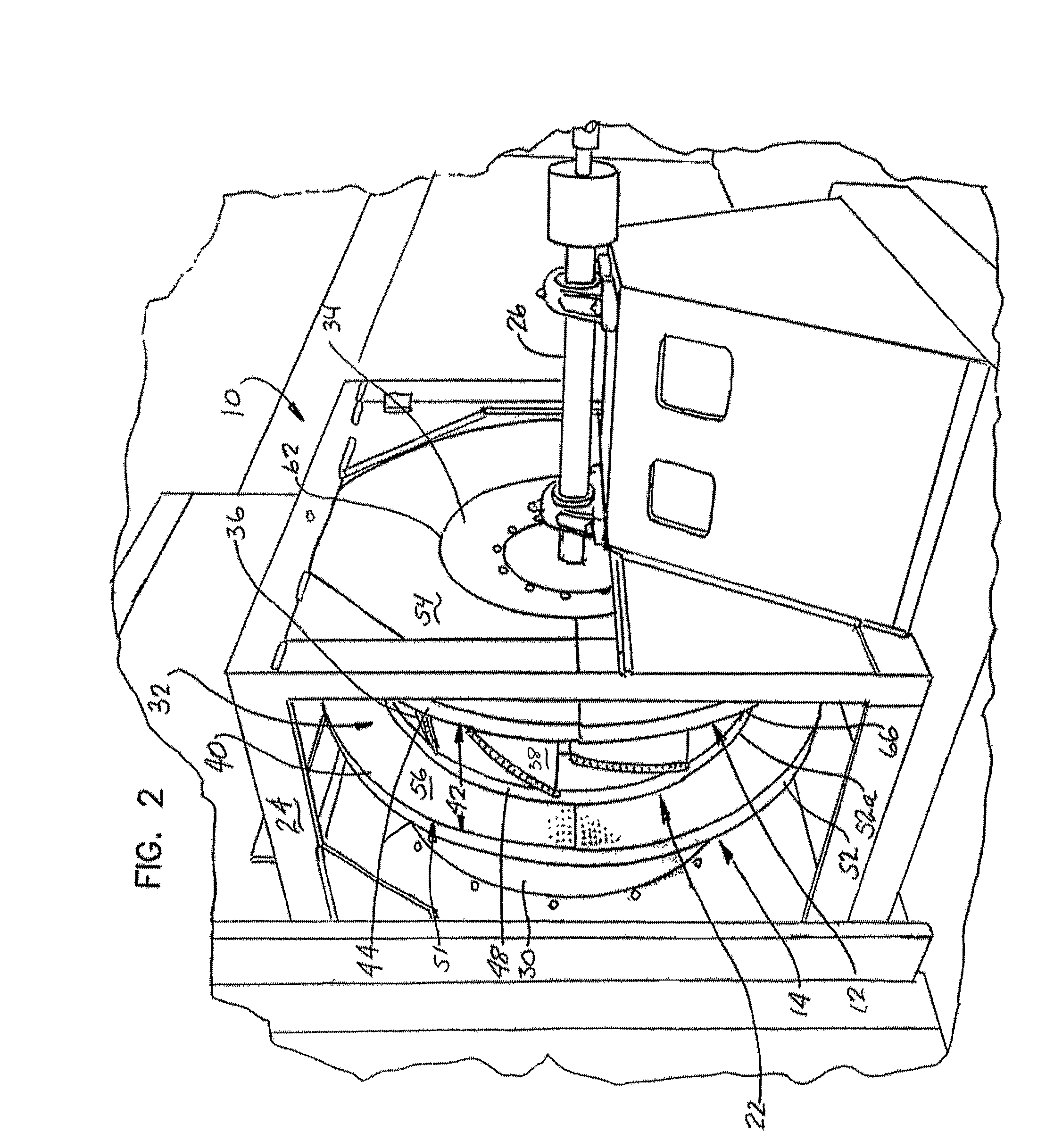
[0021]As a preliminary matter, fan assemblies 10 of the subject invention are generally shown in FIGS. 1 & 4, the assembly of FIG. 4 including features of the assembly of FIG. 1, e.g., a rear or hub diffusing structure 12, modified features of the assembly of FIG. 1, e.g., an alternately configured front or shroud diffusing structure 14, and supplemental select advantageous features, e.g., a mid-span diffusing structure 16 and / or an air inlet diffusing structure 18 optionally having an inlet tuned resonator section 20. Features of the assembly of FIG. 1 are further illustrated in FIGS. 2 & 3, and features of the assembly of FIG. 4 are selectively illustrated in FIGS. 5 & 6. Finally, aero-acoustic performance of the assembly of the subject invention in relation to conventional known fan wheel / fan assemblies is presented in FIGS. 7 & 8 vis-a-vis comparative representations of both static efficiency and specific sound power.

[0022]With reference now to FIGS. 1 & 4, preferred and optiona...


PUM


Abstract

An aero acoustic fan assembly is provided and generally includes a fan wheel, a frame, and first and second air outlet diffusing structures. The fan wheel generally, and typically includes an axial air inlet delimited by an air inlet cone, an annular air outlet, a back plate, and front plate opposite the back plate. The frame within supports the fan wheel for rotation about a central axis thereof. The first air outlet diffusing structure is supported by a portion of the frame, adjacent the back plate of the fan wheel and includes a peripheral region. The second air outlet diffusing structure is similarly supported by a portion of the frame, adjacent the front plate of the fan wheel, and also includes a peripheral region, air exiting the annular air outlet of the fan wheel passing between the peripheral regions of the diffusing structures.

Description

[0001]This is an international regular application filed under 35 U.S.C. §363 claiming priority under 35 U.S.C. §119(e)(1), of provisional application Ser. No. 60 / 604,571 having a filing date of Aug. 26, 2004.TECHNICAL FIELD[0002]The present invention generally relates to air moving assemblies, more particularly, to plenum / plug fan assemblies which boost static pressure / dynamic efficiency, and further provide noise reduction, both broadband and tone components thereof.BACKGROUND OF THE INVENTION[0003]Relatively inexpensive plenum or plug-type fans are well known in the industrial and commercial fan industry. They are commonly sold as an unhoused fan unit by the manufacturers although they are mounted in a suitable support structure that can include a front wall with an air inlet opening formed therein. These fans are used instead of, or to replace, centrifugal type fans which are commonly used in the air handling industry. The wheel of the plenum fan is used to pressurize a surround...

Claims


Application Information

Patent Timeline
Patent Type & Authority Patents(United States)
IPC IPC(8): F04D29/66
CPCF04D29/441F04D29/664
Inventor GANESH, RADHA K.WILLIAMSON, RICHARD D.WEEKS, JONATHAN C.SOLOMAKHOVA, TATYANA S.
Owner TWIN CITY FAN CO LTD
Why Eureka
Try Eureka