
Substrate cleaning apparatus and method employed therein

a cleaning apparatus and substrate technology, applied in the direction of cleaning using liquids, photosensitive materials, ways, etc., can solve the problems of high cleaning cost for the edge portion of the substrate, failure of cleaning, and improper cleaning of the clean target surface by twisted cleaning tape, etc., to achieve suppressed cleaning cost and reduce cleaning time , the effect of high speed

Inactive Publication Date: 2011-09-27
PANASONIC CORP
View PDF11 Cites 0 Cited by
  • Summary
  • Abstract
  • Description
  • Claims
  • Application Information

AI Technical Summary

Benefits of technology

"The present invention relates to a substrate cleaning apparatus for cleaning the edge portion of a substrate by using a fabric cleaning tape. The apparatus includes a moving device for moving the cleaning tape and the substrate relative to each other in a longitudinal direction of the edge portion of the substrate. The invention aims to properly clean the clean target surfaces on both sides of the edge portion of the substrate without causing cleaning failures or increasing cleaning costs. The invention also includes a compact unit for making up the cleaning tape and moving it at high speed in the longitudinal direction of the edge portion of the substrate. The invention is designed to shorten the cleaning time and suppress cleaning costs for large-scale substrates."

Problems solved by technology

This may cause a problem that the cleaning tape twists permanently or semi-permanently, and therefore the twisted cleaning tape improperly cleans the clean target surfaces.
That is, there may occur cleaning failures.
With occurrence of cleaning failures, the cleaning cost for the edge portion of the substrate becomes higher, naturally.
In this case, However, the amount of cleaning tape consumption would increase, i.e., the frequency of cleaning tape replacement would increase, so that the cleaning cost would increase.

Method used


Image

  • Substrate cleaning apparatus and method employed therein
  • Substrate cleaning apparatus and method employed therein
  • Substrate cleaning apparatus and method employed therein

Examples


first embodiment

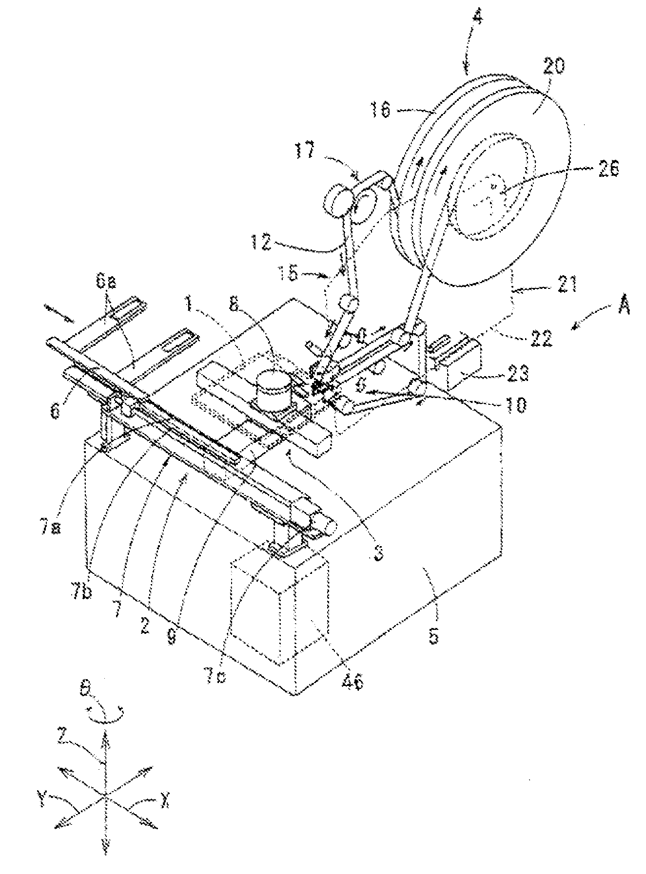
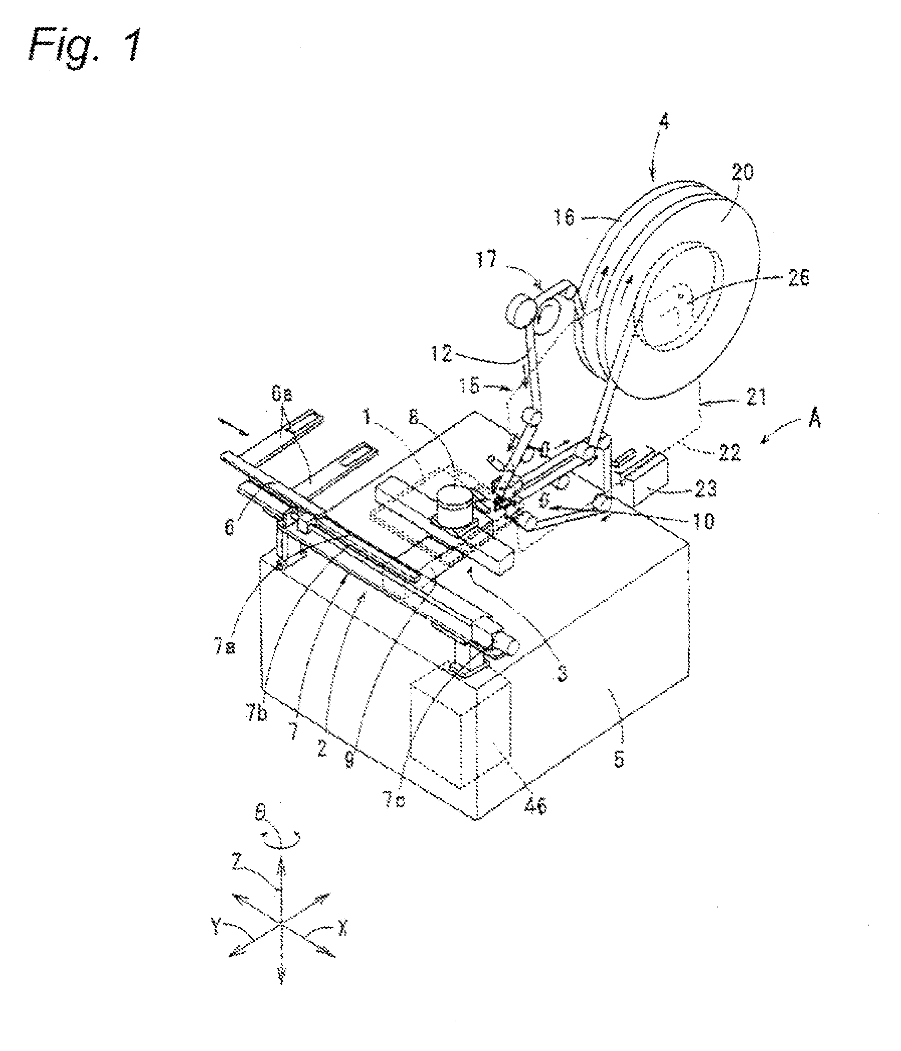
[0104]First, a substrate cleaning apparatus according to a first embodiment of the invention is described with reference to FIGS. 1 to 8. The substrate cleaning apparatus shown in FIG. 1 includes a substrate conveying device 2 for carrying a substrate 1 into the substrate cleaning apparatus, a substrate moving device 3 for moving the substrate 1 received from the substrate conveying device 2, and a cleaning mechanism 4 for cleaning clean target surfaces 1a, 1b (surfaces that need to be cleaned) positioned on front and back sides, respectively, of the edge portion of the substrate 1 (see FIGS. 4 and 5). These members are provided on a base 5. In addition, by a substrate conveying device (not shown) which is similar to the substrate conveying device 2 and which is provided in an ACF sticking apparatus (not shown), the cleaning-completed substrate 1 is carried out from the substrate cleaning apparatus and carried into the ACF sticking apparatus.

[0105]The substrate conveying device 2 ha...

second embodiment

[0179]Next, a substrate cleaning apparatus according to a second embodiment of the invention will be described with reference to FIG. 10.

[0180]The substrate cleaning apparatus of the first embodiment collects the cleaning tape 12 by winding the tape by the collecting reel 20. In contrast to this, as shown in FIG. 10, the substrate cleaning apparatus of this embodiment has, instead of the collecting reel 20, a cleaning tape collecting device 48 for collecting the cleaning tape 12, and a collecting box 49 for accommodating the cleaning tape 12 collected by the cleaning tape collecting device 48.

[0181]The cleaning tape collecting device 48 has a collecting roller 48a for pulling up the cleaning tape 12, and a pinch roller 48b for pressing the cleaning tape 12 against the collecting roller 48a. The collecting roller 48a and the pinch roller 48b are provided on the unit frame 22 of the cleaning unit 21 (incorporated in the cleaning unit 21). Also, the collecting roller 48a is so designed...

third embodiment

[0184]A substrate cleaning apparatus according to a third embodiment of the invention will be described with reference to FIG. 11.

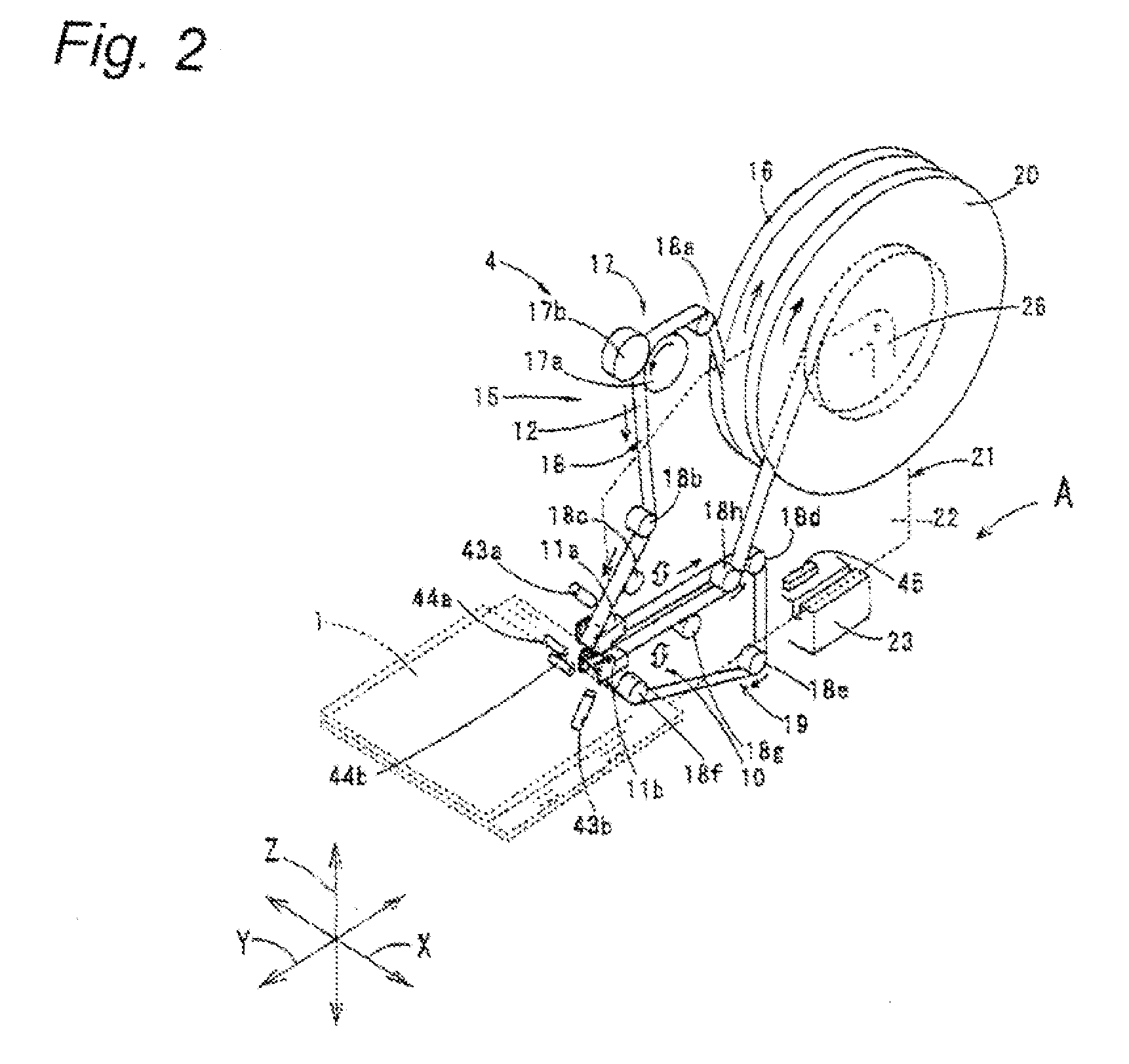
[0185]In the above-described substrate cleaning apparatus according to the first embodiment, as shown in FIG. 1 or 1, by the tape path forming member 18, the cleaning tape 12 is passed through between the presser member 11a and the clean target surface 1a and thereafter looped within the space between the substrate 1 and the feeding reel 16. In contrast to this, in the substrate cleaning apparatus of this embodiment, the cleaning tape 12 that has passed through between the presser member 11a and the clean target surface 1a is looped along the periphery (radial outside) of the feeding reel 16 by the tape path forming member 18 (plural guide rollers 18a-18h).

[0186]According to this embodiment, as apparent from comparison between FIG. 2 and FIG. 11, a distance from between the presser member 11a and the clean target surface 1a to the guide roller 18d is long...


PUM


Abstract

A substrate cleaning apparatus for cleaning a front-side clean target surface 1a and a back-side clean target surface 1b of a edge portion of a substrate 1 by wiping surfaces 12a, 12b of a cleaning tape 12. The substrate cleaning apparatus includes a presser member 11a for pressing the cleaning tape 12 against the clean target surface 1a, a presser member 11b for pressing the cleaning tape 12 against the clean target surface 1b, a tape path passing through between the presser member 11a and the clean target surface 1a and between the presser member 11b and the clean target surface 1b, a moving device for moving the cleaning tape 12 and the substrate 1 relative to each other in a longitudinal direction of the edge portion.

Description

TECHNICAL FIELD[0001]The present invention relates to a substrate cleaning apparatus, as well as a method therefor, for cleaning clean target surfaces which are surfaces to be cleaned and which are located on front and back side of a edge portion of a circuit substrate exemplified by glass substrates that are used in, for example, liquid crystal display devices and plasma display devices.BACKGROUND ART[0002]In manufacture of glass substrates, conventionally, in some cases, as shown in FIG. 13, various component parts 54 are mounted on a plurality of electrodes formed in a edge portion of a glass substrate 51. First, as shown in FIG. 13(a), clean target surfaces (surfaces that need to be cleaned), which are positioned on front and back sides of the edge portion of the glass substrate 51 in which the electrodes 52 are placed, are cleaned. Next, as shown in FIG. 13(b), an anisotropic conductive film (ACF) 53 is stuck onto the electrodes 52. Then, as shown in FIG. 13(c), component parts...

Claims


Application Information

Patent Timeline
Patent Type & Authority Patents(United States)
IPC IPC(8): B08B1/00
CPCB08B1/008Y10S134/902B08B1/30
Inventor WATANABE, MASAYAKOBAYASHI, SAKAEKABESHITA, AKIRA
Owner PANASONIC CORP
Learn More