Tomosynthesis apparatus and method to operate a tomosynthesis apparatus

a tomosynthesis apparatus and tomosynthesis technology, which is applied in the direction of instruments, diaphragms for radiation diagnostics, patient positioning for diagnostics, etc., can solve problems such as less than satisfactory manner, and achieve the effect of improving the exposure of the detector

Active Publication Date: 2011-10-04
SIEMENS HEALTHCARE GMBH
View PDF4 Cites 43 Cited by
  • Summary
  • Abstract
  • Description
  • Claims
  • Application Information

AI Technical Summary

Benefits of technology

[0013]An object of the present invention is to provide a tomosynthesis apparatus and a method to operate a tomosynthesis apparatus wherein the exposure of the detector is improved.
[0021]Since the shape of the flat panel detector is known and moreover is constant, the shape and size of the diaphragm aperture can easily be calculated. To avoid excessive calculation effort, the shape of the collimator diaphragm can be calculated using a few points in the detector plane, for example using the four corners (vertices) of the detector. An additional simplification results from the fact that the Z-coordinates of the points are predetermined both in the detector plane and in the collimator diaphragm plane by the position of the detector or, respectively, the position of the collimator diaphragm.
[0022]In the tomosynthesis apparatus according to the invention, an optimal exposure of the flat panel detector can be ensured at every tomosynthesis angle. The detector area is fully exploited and an overexposure of the detector that is undesirable for radiation protection reasons can be avoided. The tomosynthesis apparatus according to the invention ensures the largest possible image field with simultaneously the best possible radiation protection for personnel and patient.

Problems solved by technology

The collimation of the x-ray beam in tomosynthesis in which the x-ray source is moved relative to the detector has conventionally been achieved in a less than satisfactory manner.

Method used


Image

  • Tomosynthesis apparatus and method to operate a tomosynthesis apparatus
  • Tomosynthesis apparatus and method to operate a tomosynthesis apparatus
  • Tomosynthesis apparatus and method to operate a tomosynthesis apparatus

Examples


Embodiment Construction

[0042]In the following reference is made to a tomosynthesis apparatus as well as its operating method using FIGS. 1 through 7, the operating method being suitable to implement tomosynthetic examinations of the breast. A tomosynthetic examination of the breast is abbreviated in the following as a tomosynthesis. Examples of circular tomosynthesis are likewise discussed using FIGS. 8 and 9.

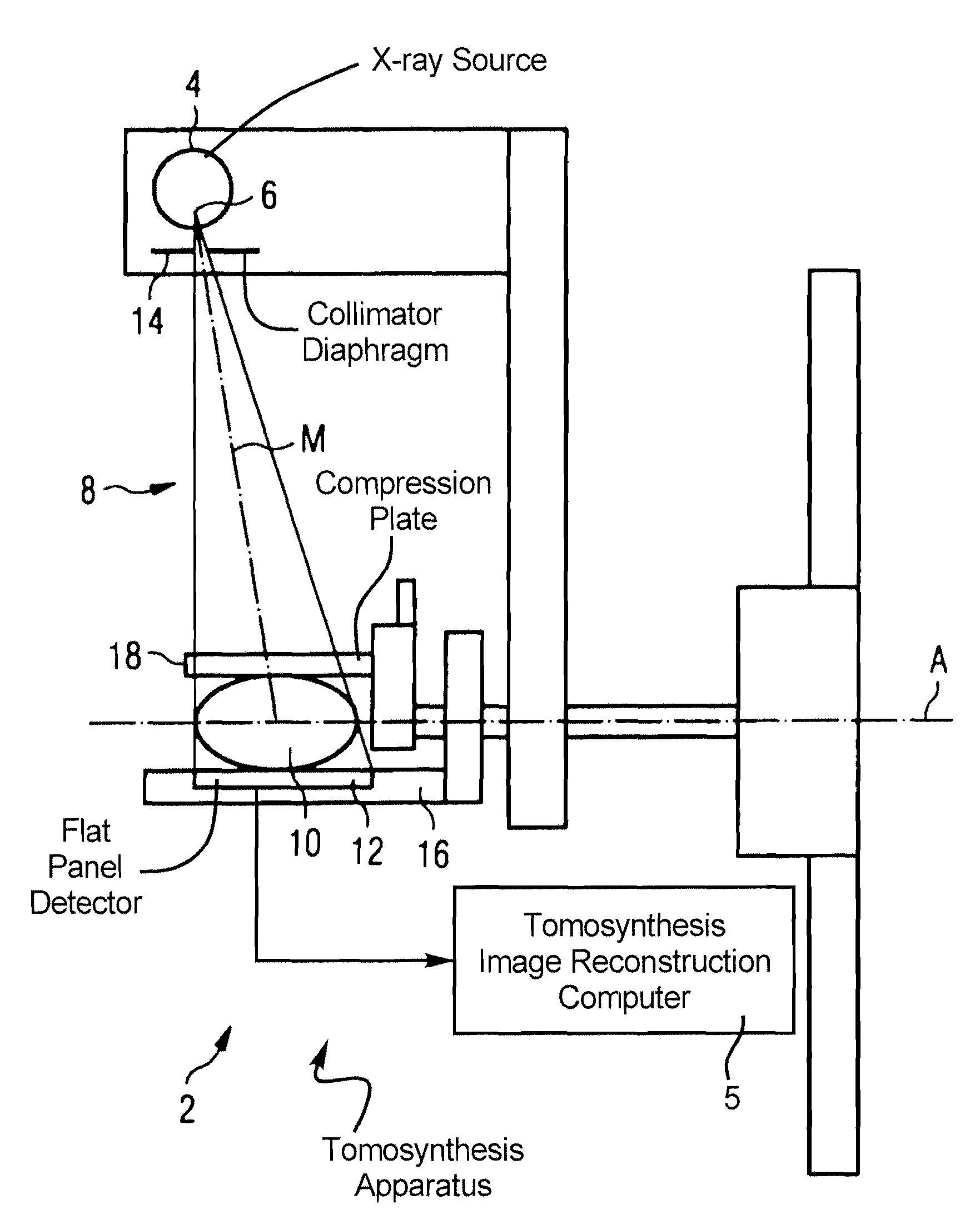
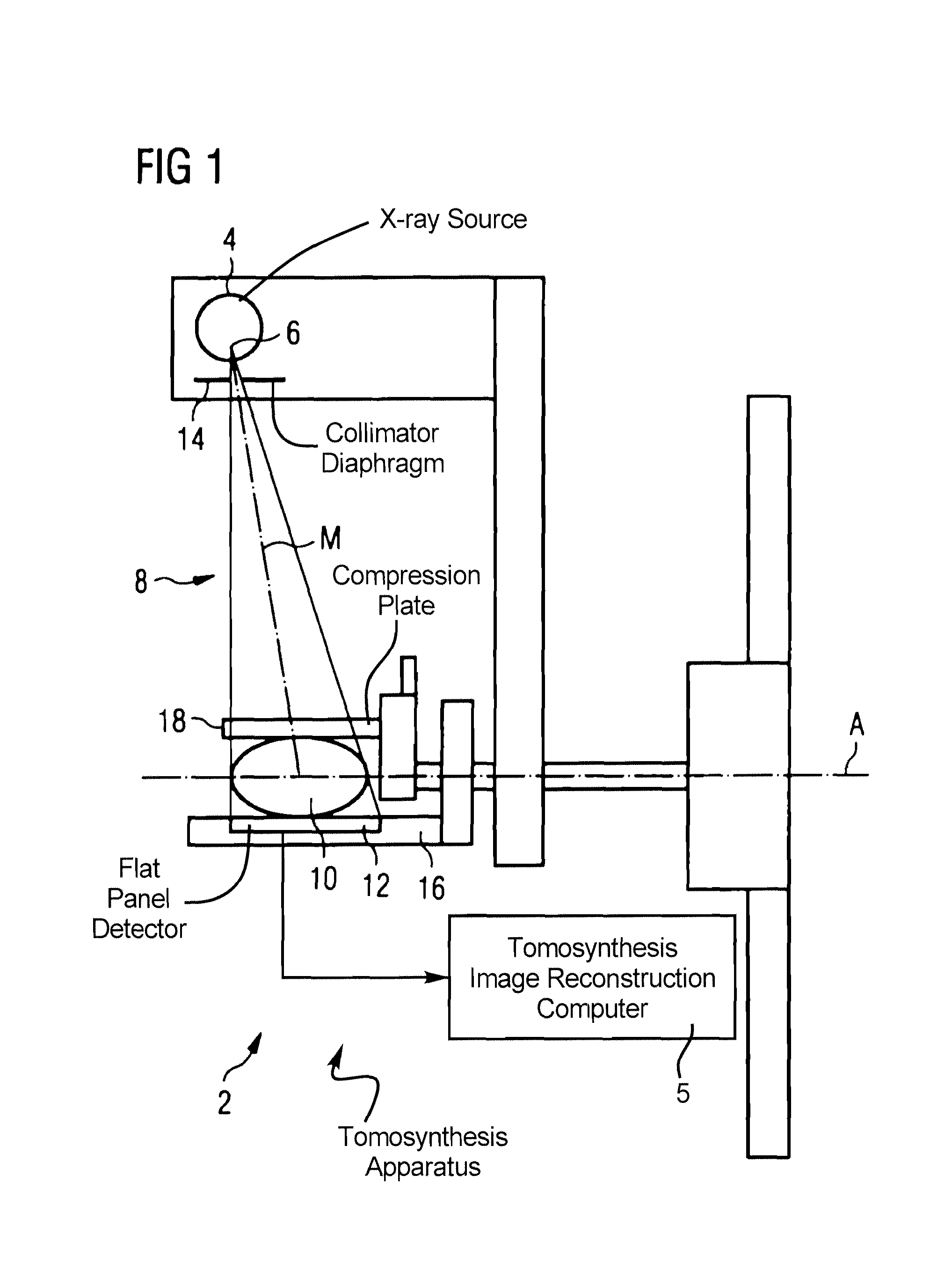
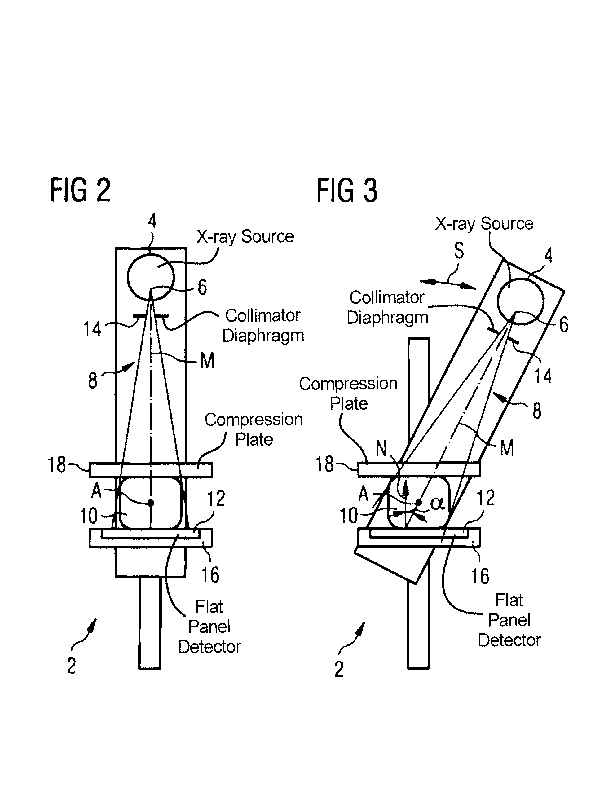
[0043]FIG. 1 shows a tomosynthesis apparatus 2 with an x-ray source 4 that generates an x-ray beam 8 emanating from its focus 6, which x-ray beam 8 irradiates a breast 10 and is received by a flat panel detector 12. The x-ray beam 8 has a central axis M. The x-ray beam 8 is bounded to the sides by the collimator diaphragm 14 mounted in the beam path between the x-ray source 4 and the flat panel detector 12. The breast 10 is compressed between a bearing plate 16 into which the flat panel detector 12 is sunk and a compression plate 18. To acquire a tomosynthesis image data set, the breast 10 is held st...


PUM

PropertyMeasurementUnit
angleaaaaaaaaaa
internal anglesaaaaaaaaaa
angleaaaaaaaaaa

Abstract

A tomosynthesis apparatus has an x-ray source that generates an x-ray beam emanating from a focus, which is received by a flat panel detector. To set a tomosynthesis angle, the position of the central axis of the x-ray beam of the x-ray source is variable. A collimator diaphragm has a diaphragm aperture that limits the expansion of the x-ray beam at the location of the flat panel detector. The collimator diaphragm is arranged in the beam path between the focus and the flat panel detector. The shape and size of the diaphragm aperture are dynamically varied (adjusted) dependent on the changing tomosynthesis angle, such that the expansion of the x-ray beam at the location of the flat panel detector always essentially corresponds to the detector dimensions.

Description

BACKGROUND OF THE INVENTION[0001]1. Field of the Invention[0002]The present invention concerns a tomosynthesis apparatus as well as a method to operate a tomosynthesis apparatus.[0003]2. Description of the Prior Art[0004]Tomosynthesis is an x-ray-based 3D imaging method which is particularly suitable for use in mammography. Through continuous development it is sought to generate x-ray images with high significance in order to differentiate benign variations from malignant variations and to reduce the number of incorrect findings, i.e. the number of suspicious findings that are caused by non-malignant variations and the number of undiscovered malignant tumors.[0005]An example of a tomosynthesis apparatus and operating method is described in DE 10 2006 024 413 A1.[0006]In conventional mammography, a two-dimensional single image of the compressed breast is generated. In tomosynthesis of the breast, single images (projections) are respectively acquired from different directions, from wh...

Claims


Application Information

Patent Timeline
Patent Type & Authority Patents(United States)
IPC IPC(8): G01N23/00
CPCA61B6/025A61B6/06A61B6/466A61B6/502H05G1/70A61B6/4028
Inventor LUDWIG, JASMINAMERTELMEIER, THOMAS
Owner SIEMENS HEALTHCARE GMBH
Why Eureka
Try Eureka