Suction brush for vacuum cleaner

a vacuum cleaner and suction brush technology, which is applied in the direction of carpet cleaners, carpet sweepers, cleaning equipment, etc., can solve the problems of reducing the suction force of the suction brush, not easy to remove hair or pet fur stuck in the carpet, and the rotation of the turbine, so as to minimize the resistance between the rib and the surface to be cleaned

Active Publication Date: 2011-10-11
SAMSUNG ELECTRONICS CO LTD
View PDF10 Cites 13 Cited by
  • Summary
  • Abstract
  • Description
  • Claims
  • Application Information

AI Technical Summary

Benefits of technology

[0009]Embodiments of the present disclosure have been developed in order to substantially solve the above and other problems associated with the conventional arrangement and provide the objectives listed below. An aspect of embodiments of the present disclosure is to provide a suction brush for a vacuum cleaner that can remove hair or animal fur that is stuck on a surface to be cleaned with the deterioration of a suction force in the suction brush prevented.
[0011]The hair removing unit may comprise a cam member, rotatably installed in the brush main body, for receiving a drive force generated by rotation of the first or second wheel; a movable member for moving forward and backward with respect to a moving direction of the brush main body in accordance with a rotation of the cam member; and a rib, coupled to a lower part of a front end of the movable member, for raking up the hair on the surface to be cleaned. The cam member could, for example, be mechanically coupled to a geared drivetrain of which the first wheel, the second wheel, or both wheels are parts. In such a mechanical coupling a drive force applied to the first and / or second wheel is transmitted via the geared drivetrain to the cam member, thereby effecting movement of the cam member.
[0014]The rib may be formed to be rounded toward the suction port as it gets from its upper end to its lower end, or may be formed to be inclined toward the suction port as it gets from its upper end to its lower end, so that resistance between the rib and the surface to be cleaned is minimized when the rib support unit moves forward, while the hair is effectively raked up toward the suction port when the rib support unit moves backward.

Problems solved by technology

Air being sucked through the suction flow path at high speed results in the rotation of the turbine.
In this case, however, since the turbine is arranged on the suction flow path, it disturbs the flow of the sucked air, and thus the suction force in the suction brush is lowered.
Through this suction brush structure, however, it is not easy to remove hair or pet fur stuck in a carpet.
Although this structure is advantageous in removing foreign materials inserted in mat textures, it is improper for raking up hair stuck in a carpet and moving the raked hair toward a suction port.

Method used


Image

  • Suction brush for vacuum cleaner
  • Suction brush for vacuum cleaner
  • Suction brush for vacuum cleaner

Examples


Embodiment Construction

[0021]Exemplary embodiments of the present disclosure will now be described in detail with reference to the annexed drawings. In the following description, detailed descriptions of known functions and configurations incorporated herein have been omitted for conciseness and clarity.

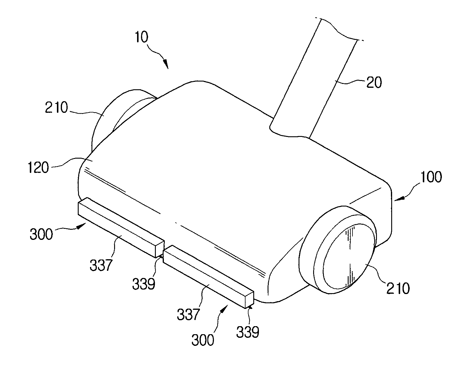
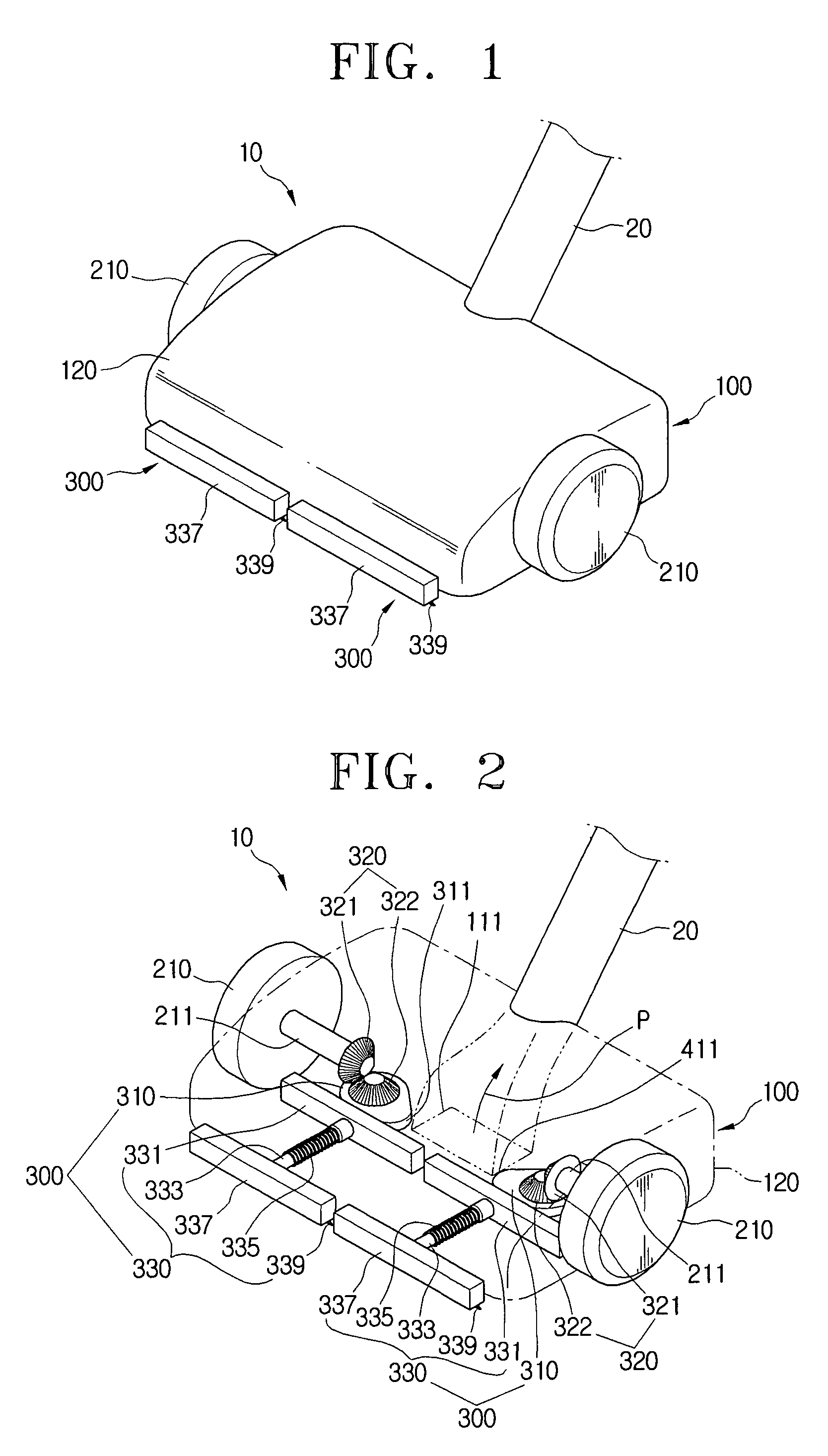
[0022]Referring to FIGS. 1 and 2, a suction brush 10 according to an embodiment of the present disclosure includes a brush main body 100, first and second wheels 210 and 220, and first and second hair removing units 300.

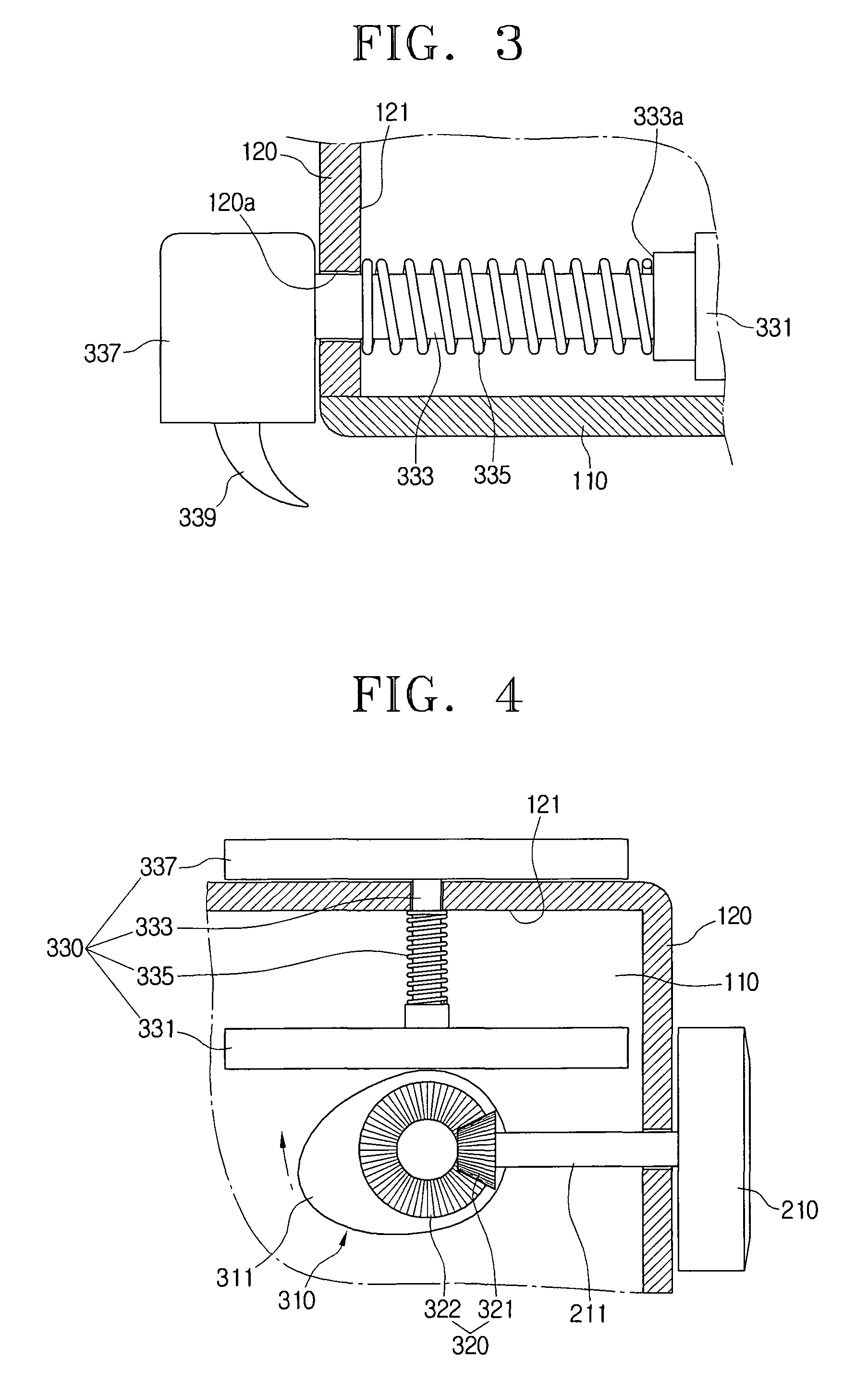
[0023]The brush main body 100 is provided with an upper housing 120 and a lower housing 110 (see FIG. 3). The lower housing 110 has a dust suction port 111, formed on a bottom surface thereof, for sucking in dust, and the upper housing 120, which is coupled to the lower housing 10, is connected to one end of an extension tube 20 the other end of which is connected to a cleaner main body (not illustrated) of a vacuum cleaner. In this case, the brush main body 100 has a suction flow path P, f...


PUM


Abstract

A suction brush for a vacuum cleaner is provided. The suction brush a vacuum cleaner includes a brush main body connected to a cleaner main body and having a dust suction port provided on a bottom surface of the brush main body, first and second wheels rotatably engaged with both sides of the brush main body, and at least one hair removing unit, arranged in front of the suction port of the brush main body, for receiving rotation drive forces from the first and second wheels and raking up hair existing on a surface to be cleaned toward the dust suction port.

Description

CROSS-REFERENCE TO RELATED APPLICATIONS[0001]This application claims the benefit under 35 U.S.C. §119 of Korean Patent Application No. 2007-72678, filed 20 Jul. 2007 in the Korean Intellectual Property Office, the entire disclosure of which is incorporated herein by reference.BACKGROUND OF THE INVENTION[0002]1. Field of the Invention[0003]The present disclosure relates generally to a suction brush for a vacuum cleaner. More particularly, the present disclosure relates to a suction brush for a vacuum cleaner which facilitates the removal of hair or animal fur that is deeply stuck in a carpet and the like.[0004]2. Description of the Related Art[0005]Generally, a vacuum cleaner is composed of a cleaner main body and a suction brush, which is separably connected to the main body through a connection tube and a flexible hose, or is directly hinge-engaged with the main body. This suction brush sucks in dust and other foreign materials using a suction force generated by a suction motor ins...

Claims


Application Information

Patent Timeline
Patent Type & Authority Patents(United States)
IPC IPC(8): A47L9/04
CPCA47L9/0422A47L9/0483A47L9/0433A47L9/06A47L9/02
Inventor SEO, JI-HO
Owner SAMSUNG ELECTRONICS CO LTD
Why Eureka
Try Eureka