
Method for operating a two-for-one twisting or cabling machine and two-for-one twisting or cabling machine

a technology of two-for-one twisting or cabling machine, which is applied in the direction of yarn, thin material processing, textiles and papermaking, etc., can solve the problems of not inconsiderable quantity of yarn remaining, residual feed bobbins remaining, etc., and achieve the reduction of operating costs, the effect of reducing the number of residual feed bobbins and reducing energy requirements

Inactive Publication Date: 2011-10-11
SAURER GERMANY GMBH & CO KG
View PDF11 Cites 7 Cited by
  • Summary
  • Abstract
  • Description
  • Claims
  • Application Information

AI Technical Summary

Benefits of technology

"The present invention aims to improve a method for operating a two-for-one twisting or cabling machine by reducing the operating outlay and minimizing the number of residual feed bobbins. This is achieved by providing a method where the feed bobbin on the spindle has half the weight of the take-up bobbin to be produced. The use of feed bobbin with half the weight of the take-up bobbin reduces the incidence of residual feed bobbin, simplifies the process of replacing the feed bobbin and takes away the need for a residual feed bobbin in the creeling device. The creeling device should preferably be equipped with at least one feed bobbin that matches the weight of the take-up bobbin. The diameter of the spindle should be adapted to the reduced feed bobbin to reduce the space requirement and energy consumption. The reduction in the spindle size also increases the service life of the machine and allows for finer yarn counts at higher rotational speeds."

Problems solved by technology

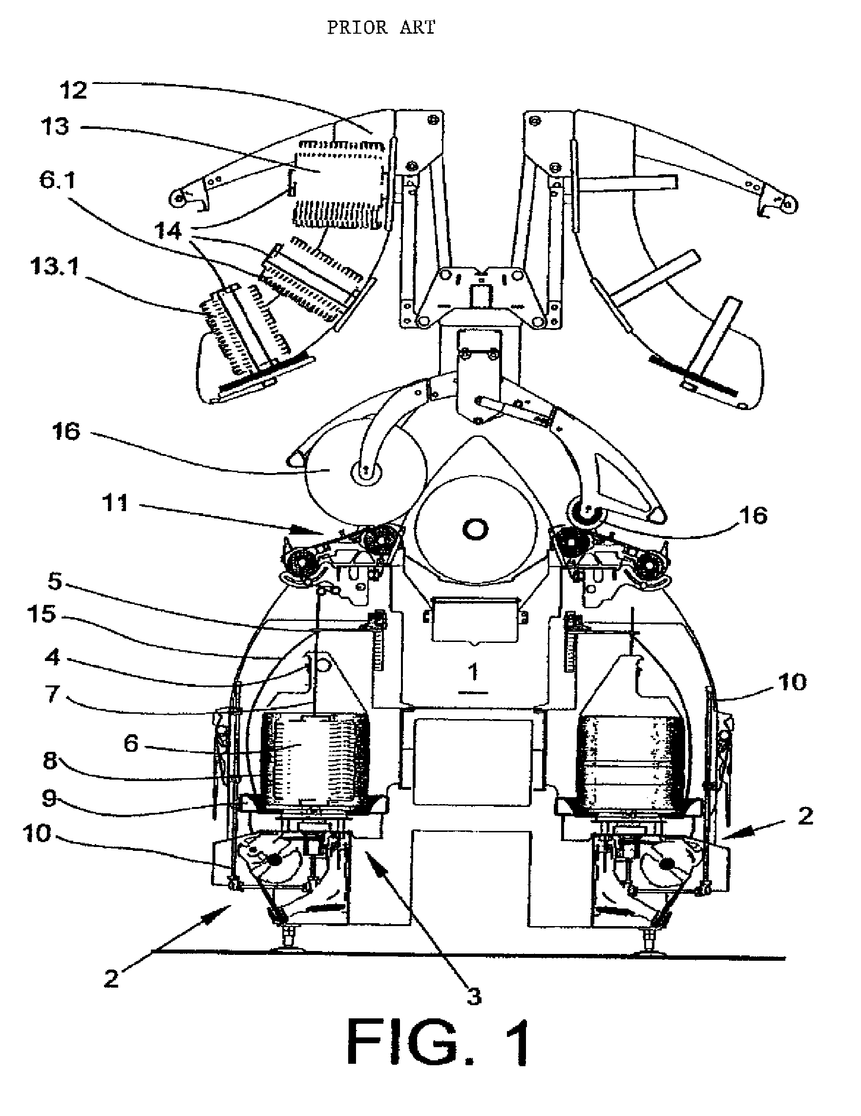
During production, a not inconsiderable quantity of yarn therefore remains on the feed bobbin creeled on the spindle, which is, however, insufficient, after the completed take-up bobbin has been replaced by an empty tube, to again wind the latter to form a take-up bobbin with the required weight.
It has proven to be disadvantageous in this procedure that, on the one hand, a large number of operating steps is necessary to wind a take-up bobbin of a predetermined weight and that, on the other hand, residual feed bobbins remain, the yarn material of which, after the ending of a batch, have to be processed as residual bobbins or discarded.

Method used


Image

  • Method for operating a two-for-one twisting or cabling machine and two-for-one twisting or cabling machine
  • Method for operating a two-for-one twisting or cabling machine and two-for-one twisting or cabling machine
  • Method for operating a two-for-one twisting or cabling machine and two-for-one twisting or cabling machine

Examples


Embodiment Construction

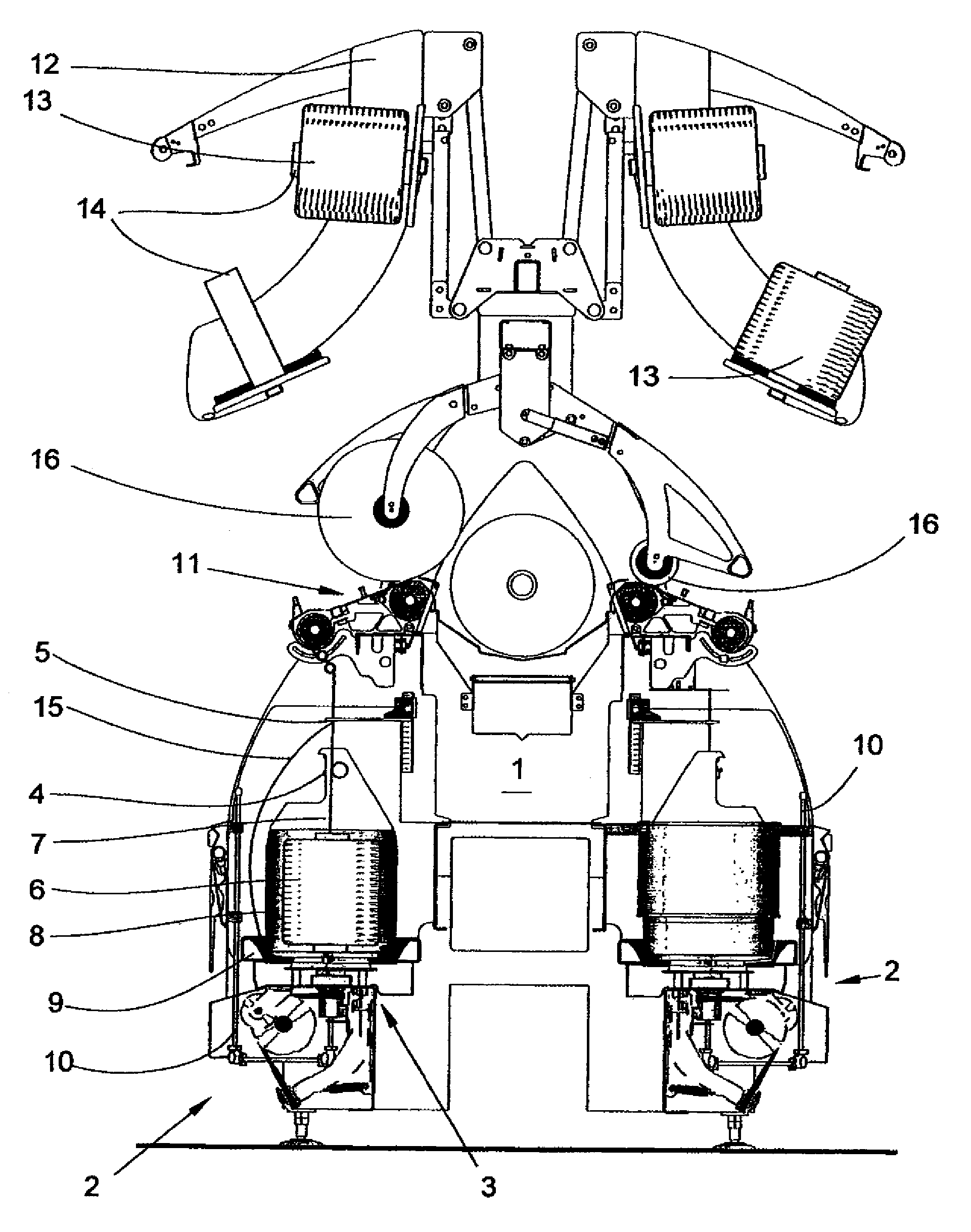
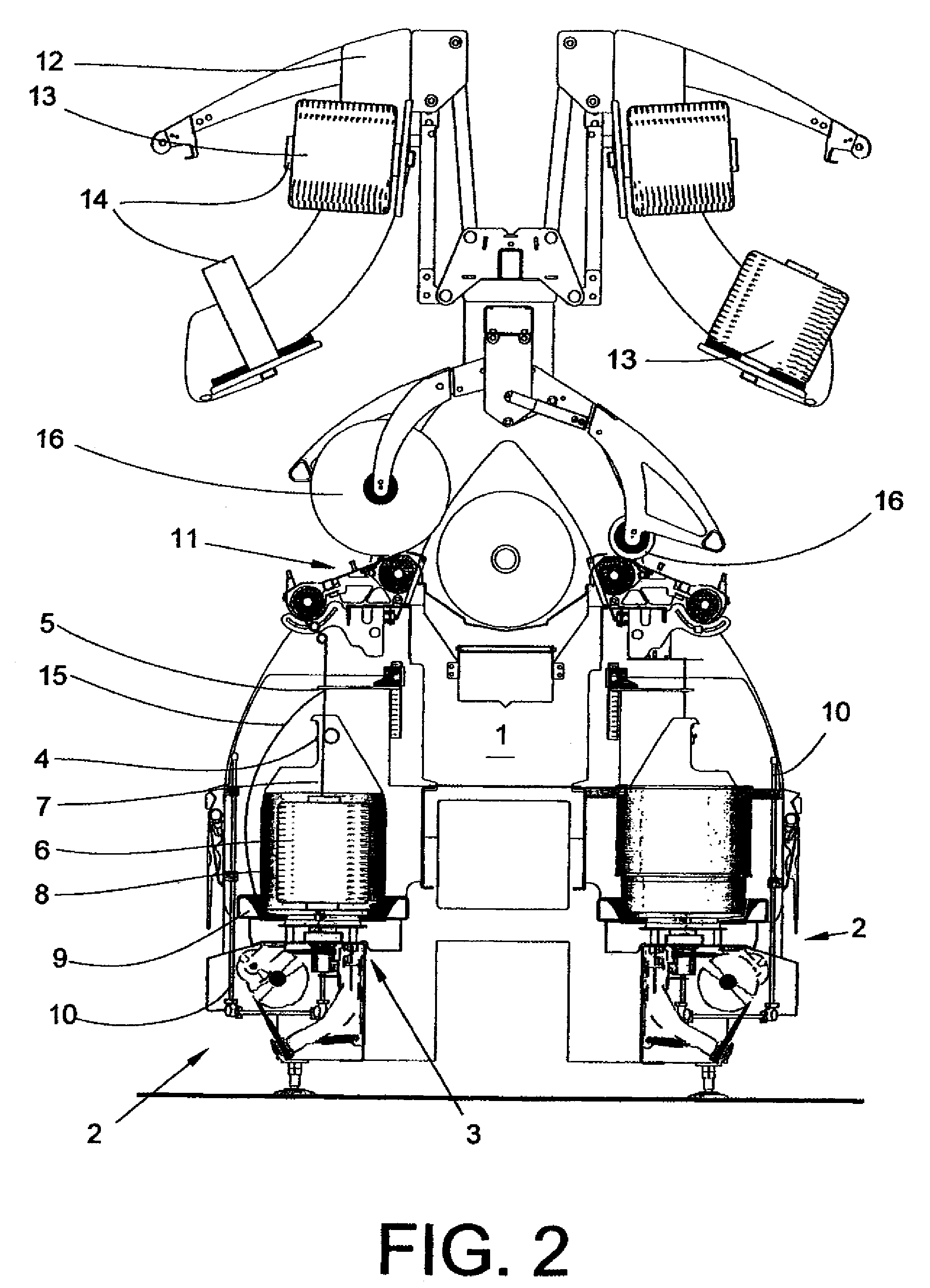
[0017]FIG. 1 shows a schematic cross-sectional view of a cabling machine 1 which has a large number of workstations 2 arranged next to one another in the longitudinal direction of the machine. The workstations 2 in each case comprise a cabling spindle 3 with a spindle pot 8 and a drivable yarn storage disc 9 arranged below the spindle pot 8. Arranged above the cabling spindle 3 are a yarn brake 4 and a balloon guide 5. The spindle pot 8 is used to receive a first feed bobbin 6, from which a yarn 7 is drawn off overhead. The yarn 7 of the feed bobbin 6 is guided via the yarn brake 4 to the balloon guide 5. Each workstation 2 has a creeling device for feed bobbins located outside the spindle pot 8, a so-called bobbin creel 12, which is set up to receive at least a second feed bobbin 13.

[0018]For this purpose, the bobbin creel 12 has a plurality of mandrels 14. A yarn 15, which is guided axially from below through the hollow axle of the cabling spindle 3, is drawn off from a second fee...


PUM

PropertyMeasurementUnit
diameteraaaaaaaaaa
diameteraaaaaaaaaa
weightaaaaaaaaaa

Abstract

Method for operating a two-for-one twisting or cabling machine (1) with multiple workstations (2), each equipped with at least two feed bobbins (6, 13), one feed bobbin (6) being creeled on a spindle (3) of the workstation (2) and at least one further feed bobbin (13) being creeled on a creeling device (12) associated with the workstation (2). The yarns (7, 15) of the feed bobbins (6, 13) are guided together in a balloon yarn guide (5) and cabled, and the cabled yarn is wound to form a take-up bobbin (16). The feed bobbin (6) creeled on the spindle (3) has half the weight of the take-up bobbin (16) to be produced and the dimensions of the spindle (3) are adapted to the diameter of the reduced feed bobbin (6).

Description

CROSS-REFERENCE TO RELATED APPLICATIONS[0001]This application claims the benefit of German patent application 10 2007 043 352.4, filed Sep. 12, 2007, herein incorporated by reference.FIELD OF THE INVENTION[0002]The present invention relates to a method for operating a two-for-one twisting or cabling machine and to a two-for-one twisting or cabling machine.BACKGROUND OF THE INVENTION[0003]A method for operating a cabling machine of the type mentioned at the outset is known from German Patent Publication DE 27 26 603 A1. The cabling machine known from German Patent Publication DE 27 26 603 A1 has a large number of workstations, which are arranged next to one another in the longitudinal direction of the machine. The workstations in each case comprise a spindle, onto which a feed bobbin is creeled as well as a creeling device arranged on the machine frame, which is used to receive a second feed bobbin. The yarn drawn off from the feed bobbin on the creeling device is guided to a yarn gu...

Claims


Application Information

Patent Timeline
Patent Type & Authority Patents(United States)
IPC IPC(8): D01H1/10
CPCD01H1/10D02G3/285
Inventor LEUPERS, WOLFGANG
Owner SAURER GERMANY GMBH & CO KG
Learn More