Impeller

a technology of impellers and bushings, applied in the field of impellers, can solve the problems of difficult to achieve the quality of impellers, and achieve the effect of improving the durability of the die, preventing the damage of the die and the bush, and increasing the strength of the blad

Inactive Publication Date: 2011-10-11
SIGMA CO LTD +1
View PDF11 Cites 0 Cited by
  • Summary
  • Abstract
  • Description
  • Claims
  • Application Information

AI Technical Summary

Benefits of technology

[0013]To avoid this problem, the axial orientation of the metallic boss a is confirmed visually when molding of the impeller is complete. However, it is extremely difficult to assess the difference between the two axial ends of the metallic boss a instantly through visual confirmation alone. Hence, the problem (technical problem or object) to be solved by the present invention is to prevent defects during the manufacture of an impeller using an extremely simple constitution, and when a defect occurs, to enable instant visual confirmation of the defect.
[0027]According to the invention described in claim 5, the tip end surface of the circumferential protruding portion is formed flat, and the underfill amount of the angular portion with the outer peripheral side face is no more than 0.3 mm. Hence, the strength of the tip end portion of the thin circumferential protruding portion can be secured, the joint surface with the resin portion of the impeller can be increased in size, and the joining strength of the resin portion can be increased. Furthermore, a thin edge portion on the resin portion of the molded impeller at the tip end portion of the circumferential protruding portion can be made extremely small or substantially eliminated, and therefore the thin edge portion can be prevented from peeling, expanding and contracting during a cooling / heating cycle, and cracking as a result of forcible insertion. Accordingly, the strength of the impeller can be secured without decreasing.

Problems solved by technology

If not, the desired performance is not exhibited, and the required level of quality as an impeller is difficult to achieve.
However, the metallic boss a can be attached to the support pillar regardless of whether the axial orientation of the metallic boss a is correct or inverted, and therefore the metallic boss a may be attached with an incorrect axial orientation.

Method used


Image

  • Impeller
  • Impeller
  • Impeller

Examples


Embodiment Construction

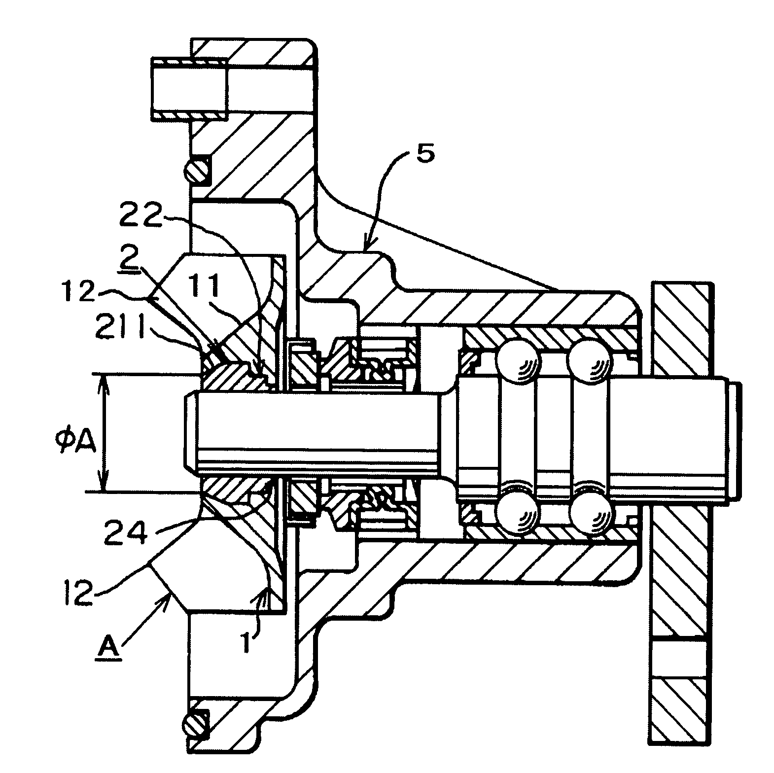
[0053]An embodiment of the present invention will be described below on the basis of the drawings. First, an impeller of the present invention will be described. As shown in FIG. 9, a drive shaft is provided rotatably on a bearing attached to a pump casing 5 of a water pump. The impeller is attached to the drive shaft, and is constituted by an impeller main body A made of synthetic resin and a bush 2 made of metal. As noted above, the impeller main body A is formed from synthetic resin, and has a V-shaped bulging portion 11 formed in the center of a disk-shaped vane portion fulcrum 1.

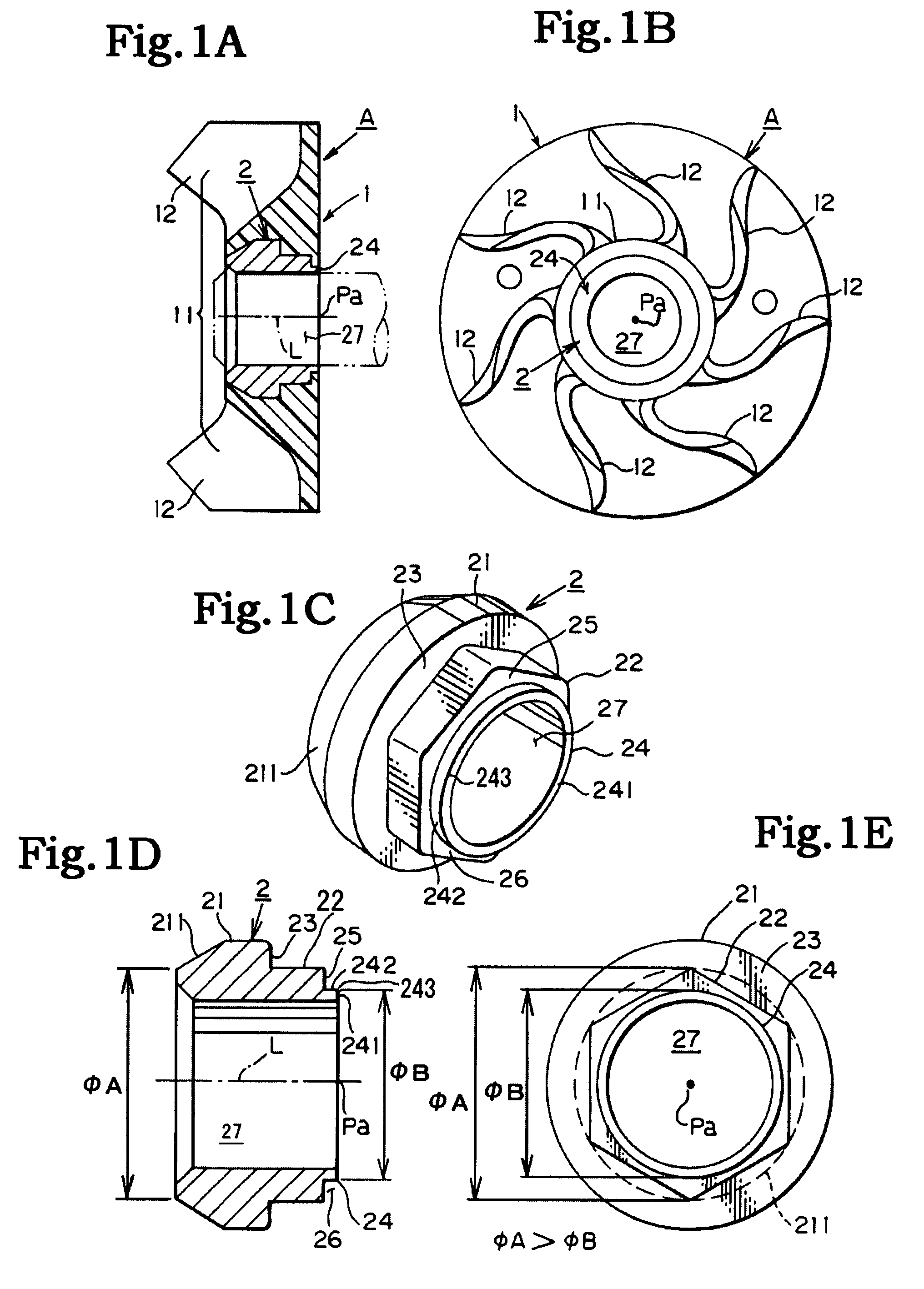
[0054]As shown in FIGS. 1A, 1B, the V-shaped bulging portion 11 is formed in a substantially truncated cone shape so as to protrude axially on the front surface side of the vane portion fulcrum 1. Further, a plurality of vanes 12, 12, . . . are formed in a substantially radial form on the periphery of the V-shaped bulging portion 11 and on the front surface side of the vane portion fulcrum 1. Here, the ...


PUM

PropertyMeasurementUnit
outer diameteraaaaaaaaaa
corner angleaaaaaaaaaa
inner diameteraaaaaaaaaa

Abstract

The present invention provides an impeller in which a metallic bush can be inserted correctly into a synthetic resin impeller main body manufactured by resin molding using a die, and a determination as to whether or not the impeller has been manufactured correctly can be made easily. The impeller comprises: a metallic bush comprising a circumferential boss portion having a substantially truncated cone-shaped throttle portion positioned on a front surface axial end side, a periaxial support boss portion positioned in an axial center, and a circumferential protruding portion positioned on a back surface axial end side; and an impeller main body made of synthetic resin and formed with a V-shaped bulging portion that bulges axially in the center of a front surface side of a disk-shaped vane portion fulcrum, in which a plurality of vanes are formed integrally on the periphery of the V-shaped bulging portion. An outer diameter of the circumferential protruding portion of the bush is formed to be smaller than an outer diameter of an axial end location of the throttle portion, the circumferential protruding portion is positioned on a back surface side of the V-shaped bulging portion, and the bush is inserted into the V-shaped bulging portion.

Description

BACKGROUND OF THE INVENTION[0001]1. Field of the Invention[0002]The present invention relates to an impeller in which a metallic bush can be inserted correctly into a synthetic resin impeller main body manufactured by resin molding using a die, and a determination as to whether or not the impeller has been manufactured correctly can be made easily.[0003]2. Description of the Related Art[0004]Conventionally, a pump such as a water pump is provided with an impeller constituted by a resin impeller main body portion formed with a plurality of vanes, and a metallic bush portion serving as a boss for supporting a drive shaft. Most of these impellers are formed by resin molding using a die. Japanese Unexamined Patent Application Publication 2003-3991 exists as an example of an impeller product formed by molding resin using a die and a core member.[0005]In the invention described in Japanese Unexamined Patent Application Publication 2003-3991, a metallic boss is inserted in and attached to ...

Claims


Application Information

Patent Timeline
Patent Type & Authority Patents(United States)
IPC IPC(8): B21D53/78
CPCB29C45/14065B29C45/842F04D29/20F04D29/2227F04D29/026B29C45/1459B29L2031/08Y10T29/49325Y10T29/49316Y10T29/49329F05D2300/10F05D2300/44
Inventor IKEDA, KAZUOOKUDA, YASUTAKAADACHI, RYOUHEIMARUYAMA, SATOSHIHOSHINO, SATOSHI
Owner SIGMA CO LTD
Why Eureka
Try Eureka