Bone replacement material

a bone replacement and material technology, applied in the field of bone replacement materials, can solve the problems of difficult to fill the cavity with a sufficient amount of bone replacement material, difficult to smoothly perform such a filling operation, and troublesome to fill the inside of the collapsed vertebral body, etc., and achieve the effect of packing or filling the operation to a bone defective par

Inactive Publication Date: 2011-10-11
HOYA CORP +1
View PDF33 Cites 14 Cited by
  • Summary
  • Abstract
  • Description
  • Claims
  • Application Information

AI Technical Summary

Benefits of technology

[0007]It is an object of the present invention to provide a bone replacement material by which a packing or filling operation to a bone defective part can be carried out smoothly, reliably and safely.

Problems solved by technology

However, it is troublesome to fill the inside of the collapsed vertebral body with a large amount of the granules of the bone replacement material each having an irregular shape.
Further, in the case where the inside of the collapsed vertebral body is filled with a granular bone replacement material using a cylindrical member, a hollow passage of the cylindrical member is likely to be clogged with the bone replacement material due to its irregular shape, so that there is a case that it is difficult to smoothly perform such a filling operation.
Furthermore, in the case where the conventional bone replacement material (comprised of granules having irregular shapes) is used, the granules of the bone replacement material introduced into the cavity of the vertebral body is likely to remain near the vicinity of an opening of the distal end of the cylindrical member, thus it is difficult to fill the cavity with a sufficient amount of the bone replacement material.
Furthermore, even when the cavity is filled with a large amount of the bone replacement material, it is difficult to increase the filling ratio sufficiently due to the presence of many gaps among the granules.
Such granules are likely to be broken when a load is applied thereto, so that the volume of the vertebral body is decreased.
As a result, it is difficult to keep the result of the operation over a long period of time.
However, when such a material is used, there is a risk that the material will flow out from the vertebral body to thereby damage adjacent nerves or block blood flow, thus problems still remain in its safeness.

Method used


Image

  • Bone replacement material
  • Bone replacement material
  • Bone replacement material

Examples


Embodiment Construction

[0072]Hereinbelow, preferred embodiments of a bone replacement material according to the present invention will be described in detail with reference to the accompanying drawings.

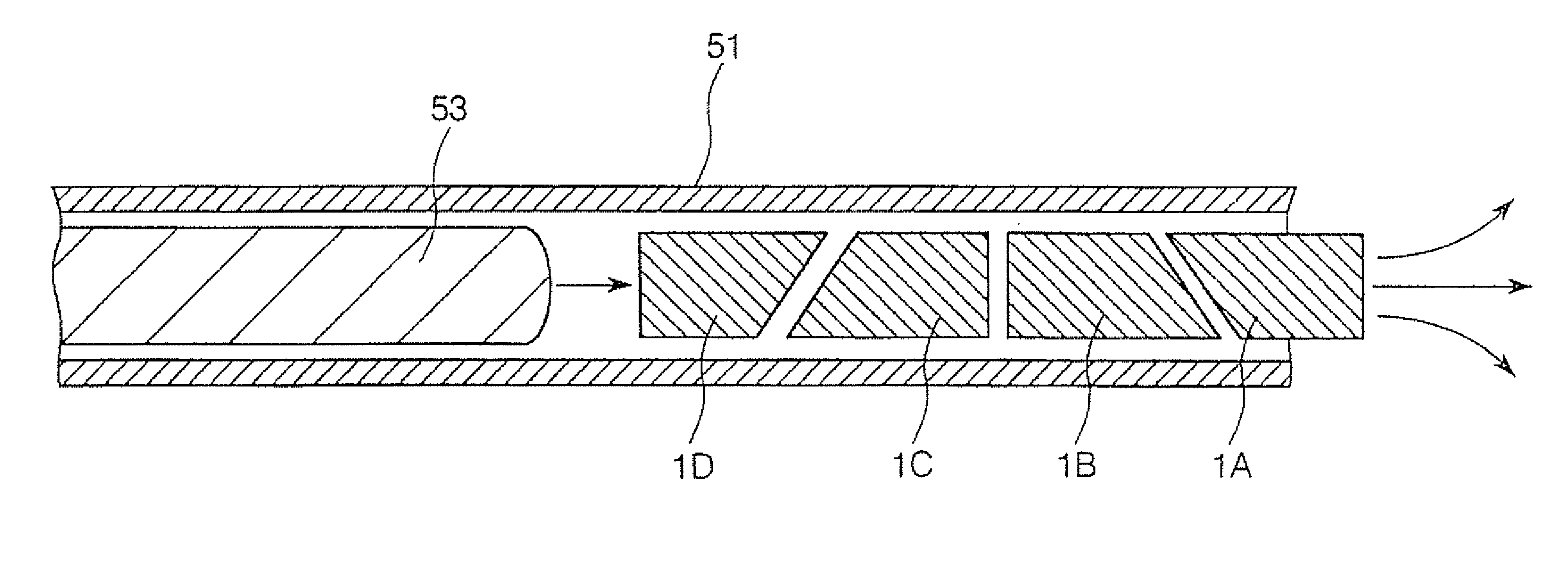
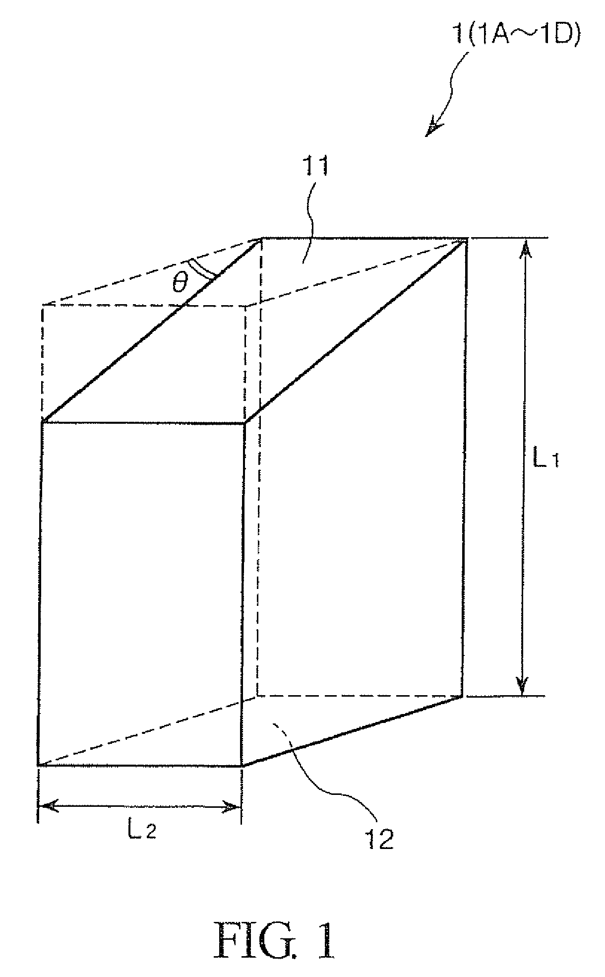
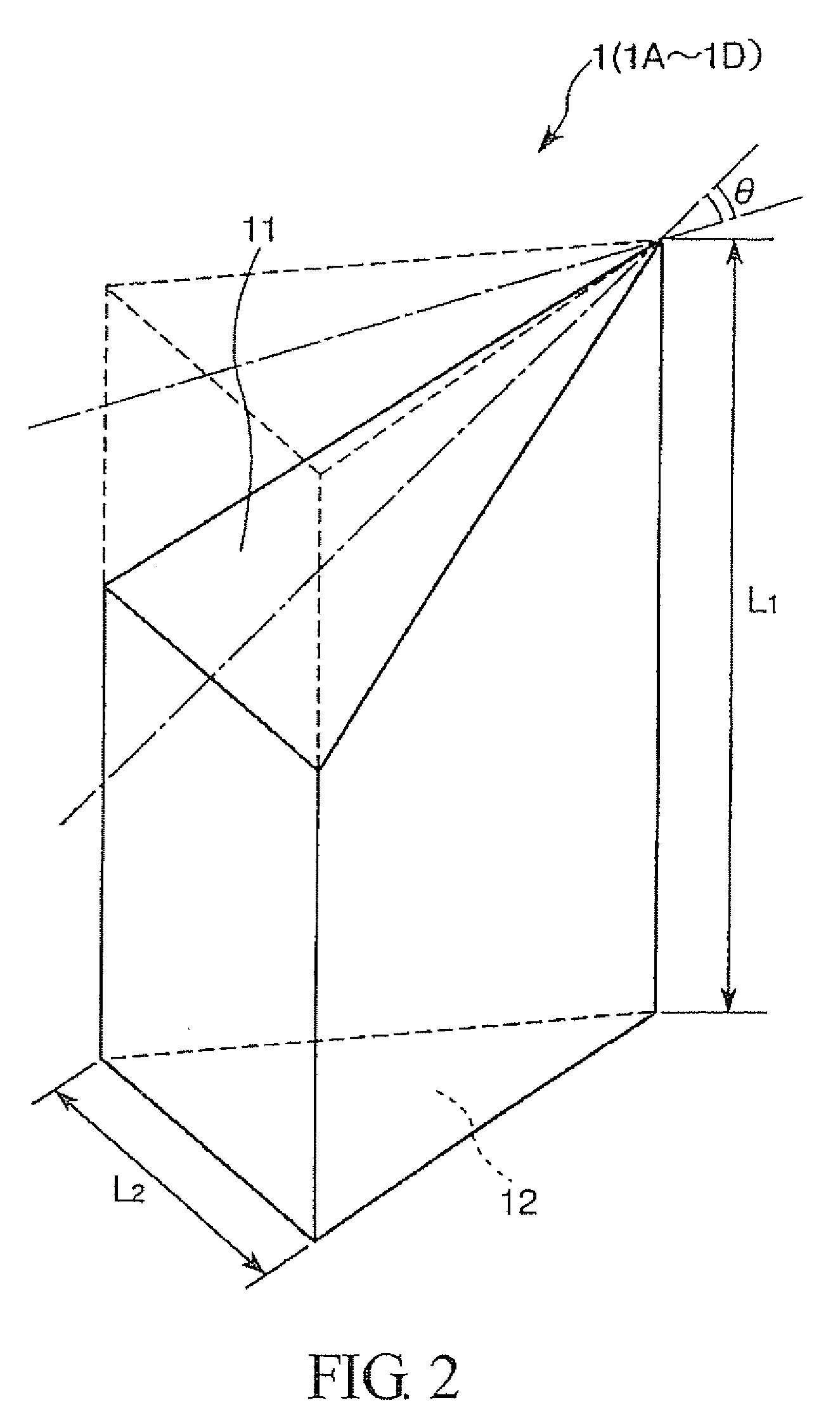
[0073]FIG. 1 is a perspective view which shows a preferred embodiment of a bone replacement material according to the present invention. The bone replacement material of the present invention is used by being packed into a bone defective part.

[0074]In this regard, it is to be noted that the term “bone defective part” in this specification means a cavity formed in a bone due to various causes such as external injuries, an operation for removal of a tumor, decreased bone density due to osteoporosis, or combination of these causes.

[0075]The bone replacement material of the present invention is suitably used for filling a bone defective part formed in one or more of bones such as vertebral body (centrum) ilium, scapula, humerus, ulna, radius, femur, tibia and fibula. Although each of these bones has a relativel...


PUM

PropertyMeasurementUnit
angleaaaaaaaaaa
volumeaaaaaaaaaa
lengthaaaaaaaaaa

Abstract

Bone replacement material to be used by being packed into a bone defective part, wherein the bone replacement material consists essentially of a calcium phosphate based compound and is formed into a pellet and satisfies both of the following conditions (I) and (II): (I) porosity is equal to or less than 75%; and (II) collapsing strength is equal to or more than 15 Mpa. The pellet has a roughly polyhedral shape and is defined by a plurality of surfaces including a pair of opposite, non-parallel surfaces and a surface adjoining to the pair of opposite, non-parallel surfaces, one of the opposite, non-parallel surfaces being inclined at a predetermined angle with respect to the other of the opposite, non-parallel surfaces. The one of the opposite, non-parallel surfaces is non-adjoined with the other of the opposite, non-parallel surfaces in the pellet. The other of the opposite, non-parallel surfaces is perpendicular to the surface adjoining to the pair of opposite, non-parallel surfaces.

Description

TECHNICAL FIELD[0001]This invention relates to a bone replacement material.BACKGROUND ART[0002]Collapse of a vertebral body as a result of external injuries (trauma) or osteoporosis is referred to as a vertebral body compression fracture. In the method that is known for the treatment of this kind of fracture, the collapsed vertebral body is repaired by filling the inside thereof with a filler (such as a bone replacement material) through a vertebral arch using a transpedicular technique.[0003]In this treatment method, a collapsed vertebral body is first returned to a substantially original shape, that is, a collapsed vertebral body is reduced, whereby a cavity (a born defective part) is created therein. A filler such as a bone replacement material is then packed into the cavity to repair the vertebral body, or a filler is packed into the cavity to push a fragile spongy bone aside so that the inside of the collapsed vertebral body is reinforced.[0004]Conventionally, in such a treatme...

Claims


Application Information

Patent Timeline
Patent Type & Authority Patents(United States)
IPC IPC(8): A61F2/28A61L27/00A61B17/00A61B19/00A61F2/00A61F2/46A61L27/12C04B38/00
CPCA61L27/12A61B17/00234A61B2019/462A61F2/4601A61F2002/2835A61F2002/30153A61F2002/30156A61F2002/30158A61F2002/3023A61F2002/30266A61F2002/30281A61F2002/30617A61F2002/4623A61F2002/4635A61F2002/4662A61F2230/0019A61F2230/0023A61F2230/0026A61F2230/0069A61F2230/0082A61F2230/0086A61F2250/0097A61F2310/00293A61F2/4603A61L2430/02A61B2090/062A61F2/28
Inventor MATSUZAKI, HIROMITOMINAGA, YOSHIE
Owner HOYA CORP
Why Eureka
Try Eureka