Distributed control system

a control system and distribution system technology, applied in the direction of error detection/correction, instruments, computing, etc., can solve the problem of virtually losing the effect of the method

Active Publication Date: 2011-10-18
HITACHI LTD
View PDF14 Cites 5 Cited by
  • Summary
  • Abstract
  • Description
  • Claims
  • Application Information

AI Technical Summary

Benefits of technology

Enables reliable fault identification and information sharing among nodes, ensuring system reliability even in systems with only three nodes, thereby preventing contradictions and failures.

Problems solved by technology

So, the above method has a problem because if not all the variable values are the same, then naturally not all the corresponding outputs will be the same, and thus the effectiveness of the method is virtually lost.

Method used


Image

  • Distributed control system
  • Distributed control system
  • Distributed control system

Examples


embodiment 1

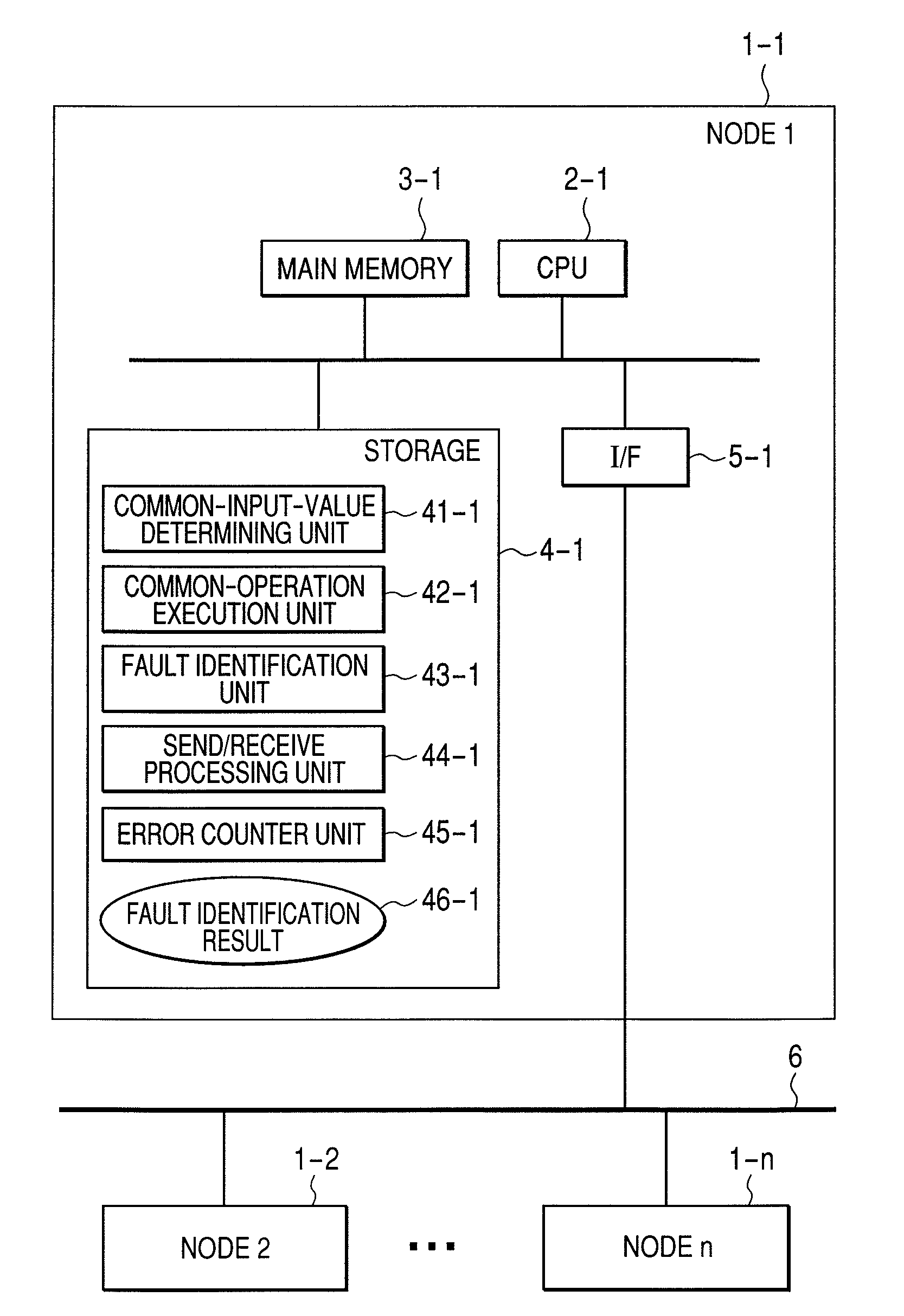
[0027]FIG. 1 is a block diagram of a distributed system.

[0028]The distributed system includes multiple nodes 1-1, . . . 1-n (n≧3), which are connected to each other via a network 6.

[0029]Each node is a processing unit that can exchange information with the other nodes via the network, and includes various electronic controls, actuators and their drivers, sensors, etc.

[0030]Each node includes a CPU 2, a main memory 3, a storage 4, and an I / F 5 connected to the network 6, and communicates with the other nodes via the network 6.

[0031]The storage 4 stores programs for a common-input-value determining unit 41, common-operation execution unit 42, fault identification unit 43, send / receive processing unit 44 and error counter unit 45 as well as various data such as fault identification result 46.

[0032]The CPU 2 performs processes by loading those programs into the main memory 3 and executing them. The programs and data as described herein may be prestored in the storage or inputted from a ...

embodiment 2

[0055]Besides the FIG. 2 procedure, fault identification by mutual node monitoring can also be achieved by a procedure shown in FIG. 6. Similarly to the FIG. 2 procedure, the FIG. 6 procedure is performed with all nodes synchronized with one another. While the mutual monitoring procedure of FIG. 2 is effective in identifying faults in sending nodes, that of FIG. 6 is effective in identifying faults in receiving nodes as well as faults in sending nodes. The procedure shown in FIG. 6 will be described below.

[0056]After steps 610-630 (similar to the steps 210-230 of FIG. 2), the fault identification unit 43 performs the ID step (step 640). Unlike the step 240 of FIG. 2, the step 640 does not perform any notification. That is, the ID result obtained at the step 640 is not used for operating the error counter or node fault flag table.

[0057]Next, the send / receive processing units 44 of all nodes exchange the ID results with one another at step 650 (hereinafter “EXC2 step”). This enables e...

embodiment 3

[0072]FIG. 9 is a block diagram of a distributed system. This system differs from the FIG. 1 system only in that the common-input-value determining unit 51 of each node is connected to an input unit 900 via a communication line 910. As for the configuration of the communication line 910, each node may be provided with a dedicated line such as a serial cable or all nodes may be connected via a single network.

[0073]The input unit 900 generates an input datum used for the mutual node monitoring procedure of FIG. 2 or 6, and delivers it to the common-input-value determining units 51. The input datum is generated from a sensor output signal or the like. Using all the input data received by all nodes or values processed therefrom at all nodes, the common-input-value determining unit 51 of each node provides a common-input-value by the IS procedure.

[0074]With the FIG. 9 configuration, the nodes can mutually monitor one another in a similar manner to that described in FIG. 2 or 6; in additi...


PUM


Abstract

There is provided a distributed system having a plurality of nodes connected by a network. Each of the nodes includes: a common-parameter-value determining unit for determining a common-parameter-value from values of a parameter (each value being possessed by a corresponding one of the nodes); a common-operation execution unit for executing a common-operation using, as its input, a value of the parameter or the common-parameter-value; a send / receive unit for exchanging, via the network, the parameter values used for the determination of the common-parameter-value and the results of the common-operation execution with the other nodes; and a fault identification unit that compares the common-operation execution results collected from all the nodes and determines that an error occurs if not all the results are the same.

Description

CLAIM OF PRIORITY[0001]The present application claims priority from Japanese patent application serial No. 2007-250410, filed on Sep. 27, 2007, the content of which is hereby incorporated by reference into this application.FIELD OF THE INVENTION[0002]The present invention relates to high reliability control systems in which multiple devices connected to a network cooperate.BACKGROUND OF THE INVENTION[0003]A type of control system configuration of is a distributed system. In distributed systems, multiple nodes (such as computers and controllers) cooperate by exchanging messages via a communication network. In such a distributed system, even when part of the system suffers from a fault, a remaining normal part can execute, on behalf the faulty part, tasks for which the faulty part has been responsible. Thus, a highly fault tolerant system can be achieved.[0004]A problem with distributed systems is fault detection. Because nodes operate independently of each other, there can occur a si...

Claims


Application Information

Patent Timeline
Patent Type & AuthorityPatents(United States)
IPC IPC(8): G06F11/00
CPCG06F11/0709G06F11/182H04L41/0677G06F11/076
InventorMATSUBARA, MASAHIROSAKURAI, KOHEISHIMAMURA, KOTAROKANEKAWA, NOBUYASU
OwnerHITACHI LTD