
Distributed control system and information processing system

a control system and information processing technology, applied in the field of distributed control system, can solve the problems of difficult to guarantee the worst executing time of sensor input to actuator output, difficult inability to guarantee the real-time operatability of end-to-end, so as to improve the productivity of software, facilitate the effect of starting and reducing the labor for matching the application to the new system

Inactive Publication Date: 2006-09-05
HITACHI LTD
View PDF5 Cites 51 Cited by
  • Summary
  • Abstract
  • Description
  • Claims
  • Application Information

AI Technical Summary

Benefits of technology

This approach ensures minimal software changes, reduces labor, and improves productivity by allowing real-time operatability and efficient communication processing, even when system configurations change, while ensuring that high-priority messages are processed promptly, thus enhancing the overall system's responsiveness and reliability.

Problems solved by technology

However, in the conventional library method described above, it is difficult to guarantee the worst executing time of sensor inputting to actuator outputting including the communication processing through the network, that is, to guarantee the real time operatability of end-to-end because a communication process or the like is described in the AP module.
In other words, in a case where real-time operatability is independently guaranteed for each AP module in taking the starting timings of the AP module and communication processing into consideration, the AP module needs to be completely re-written ever change in the system configuration because the AP module does not have versatility at least in the real-time operation, and accordingly the real-time operatability of end-to-end is difficult to be guaranteed.
However, when the units of different kinds are interconnected and rewriting of the AP module on each of the units is impossible, the real-time operatability of end-to-end can not be guaranteed.
On the other hand, according to the conventional memory transcribing method described above, the worst executing time of each AP module and the worst executing time of communication processing are guaranteed because the AP module and the communication processing are separated from each other, but the data transmission delay occurs because the AP module and the communication processing are asynchronously started.
Therefore, the worst executing time from sensor input to actuator output including the communication processing through the network is not guaranteed.
From such a reason, it is considered that the conventional memory transcribing method is unsuitable for processing severe in requiring the worst executing time.

Method used


Image

  • Distributed control system and information processing system
  • Distributed control system and information processing system
  • Distributed control system and information processing system

Examples


embodiment 1

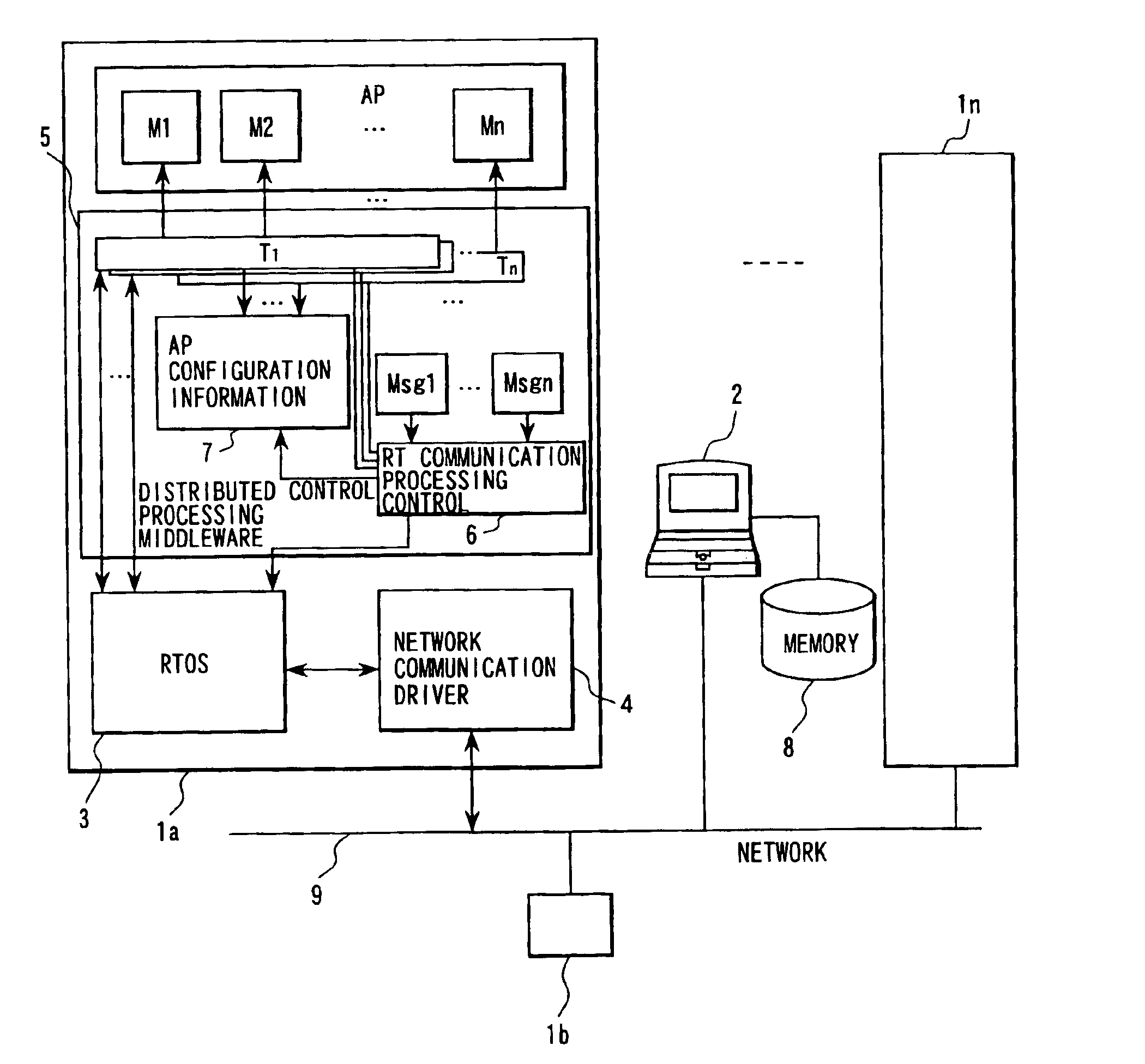
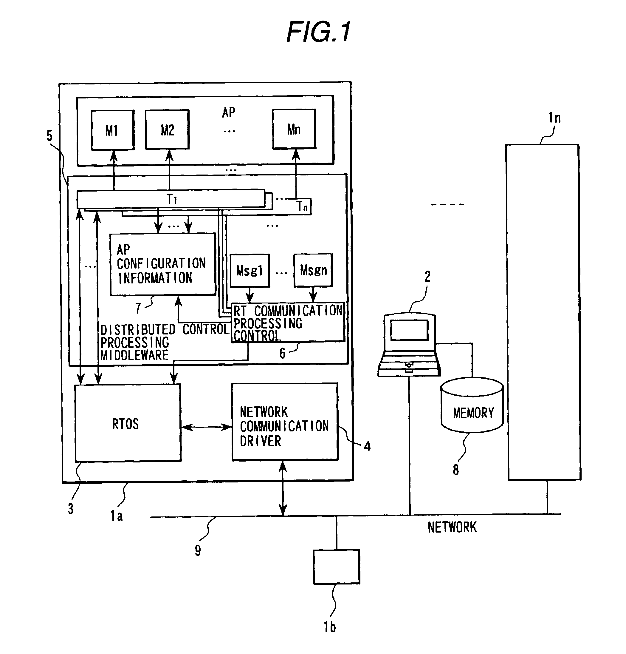
[0097]As Embodiment 1, description will be made on a case of adding and transferring units of the distributed control system shown in FIG. 1.

[0098]Initially, operation of the distributed control system shown in FIG. 1 will be described.

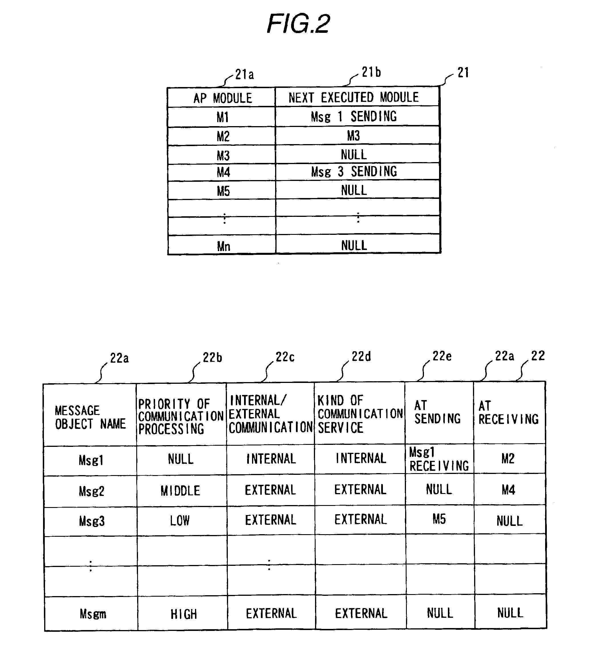
[0099]FIG. 2 shows the AP configuration information 7 which is composed of AP module configuration information 21 and message object configuration information 22.

[0100]AP modules 21a executed in the system and modules 21b executed next by the task after completion of executing the AP module 21a (sending and receiving processing of the AP module or the message object) are registered in the AP configuration information 21.

[0101]The example of the figure shows that the task is executed by executing AP module: M1 and then executing sending of message object: Msg1, and executing AP module: M2 and then executing AP module: M3. Although the next executed module after executing AP module: M3 is indicated as NULL, the indication NULL means that there is no mod...

embodiment 2

[0235]Description will be made below on automatic generation of the information of which the control structure of each control unit is defined in the distributed control system shown in FIG. 1.

[0236]FIG. 21 shows the flow of automatic generation by an information processing system 2. The information processing system 2 automatically generates the AP configuration information 7 and the message objects based on user defined information of input information from a user by loading and executing a program stored in an external memory 8, that is, an information analyzing tool 2108.

[0237]Before explaining details of the automatic generating processing, information ((1) user defined information, (2) AP configuration information, (3) message object) in connection with the processing will be described.

(1) User Defined Information

[0238]The user defined information includes three kinds of information, that is, system configuration information 2120, unit configuration information 2121 and system...

embodiment 3

[0348]Description will be made below on a configuration which improves real-time operatability of message sending in the distributed control system.

[0349]FIG. 51 shows the configuration of a real-time distributed system. In the distributed control system, control units 5000 and 5060 are connected with a network 5005. As the network of the present invention used is a CAN (controller area network) described, for example, in Specification of DeviceNet, volume 1, Release 2.0, 1998, chapter 2 section 2.1 to 2.8, published by Open DeviceNet Vendor Association. The control unit 5000 is composed of a CPU 2001, a memory 5002 and a CAN controller 5003 which are connected with a bus 5003. The CAN controller 5003 is connected to a CAN controller contained in the other control unit 5060 through the network 5005. The memory 5002 stores an application program 5006, an OSEK-COM 5008, a CAN driver 5009 and an OS 5050. Here, the OSEK-COM is a program for processing OSEK-COM protocol which is describe...


PUM


Abstract

In a real-time distributed control system in which a plurality of network controllers are connected, a middleware module in each control unit executes starting of application modules and calling RT communication processing according to starting order information in application configuration information. RT communication service sends and receives messages between the application modules corresponding to the calling. The application configuration information and the messages are generated by an information processor based on user defined information, and transmitted to each of the units. A network driver executes network communication using a network controller which stores sending and receiving messages. A network driver priority manager determines priority of processing of the network driver corresponding to priorities of sent and received messages, and a scheduler executes processing of the network driver according to the priority of the processing of the network driver.

Description

BACKGROUND OF THE INVENTION[0001]The present invention relates to a distributed control system in which a plurality of built-in systems are connected with a field network such as a CAN (controller area network), a foundation field bus or the like.[0002]A distributed control system in which a plurality of built-in systems are connected with a field network has been applied to a power train control system of a vehicle, a field instrument control system of factory automation or process automation, a control system of a medical instrument or a robot.[0003]In an LON (local operating network) of a kind of field networks or in a standard communication protocol for automobile control OSEK-COM), a library method is employed. In the library method, an application program module (hereinafter, referred to as AP module) calls communication processing. A technology in connection with the library method is described, for example, in “OSEK / VDX Communication Version 2.0a (edited by OSEK group)”.[000...

Claims


Application Information

Patent Timeline
Patent Type & Authority Patents(United States)
IPC IPC(8): G06F15/177H04L29/08
CPCH04L67/125H04L69/329H04L67/10
Inventor SUZUKI, SHOJI
Owner HITACHI LTD
Learn More