Flat panel array antenna

a flat panel array and antenna technology, applied in the field of microwave antennas, can solve the problems of increasing overall costs, preventing simultaneous efficient alignment of the link for both channels, and resonant configurations typically cannot achieve the requisite electromagnetic characteristics

Active Publication Date: 2013-10-15
COMMSCOPE TECH LLC
View PDF87 Cites 51 Cited by
  • Summary
  • Abstract
  • Description
  • Claims
  • Application Information

AI Technical Summary

Benefits of technology

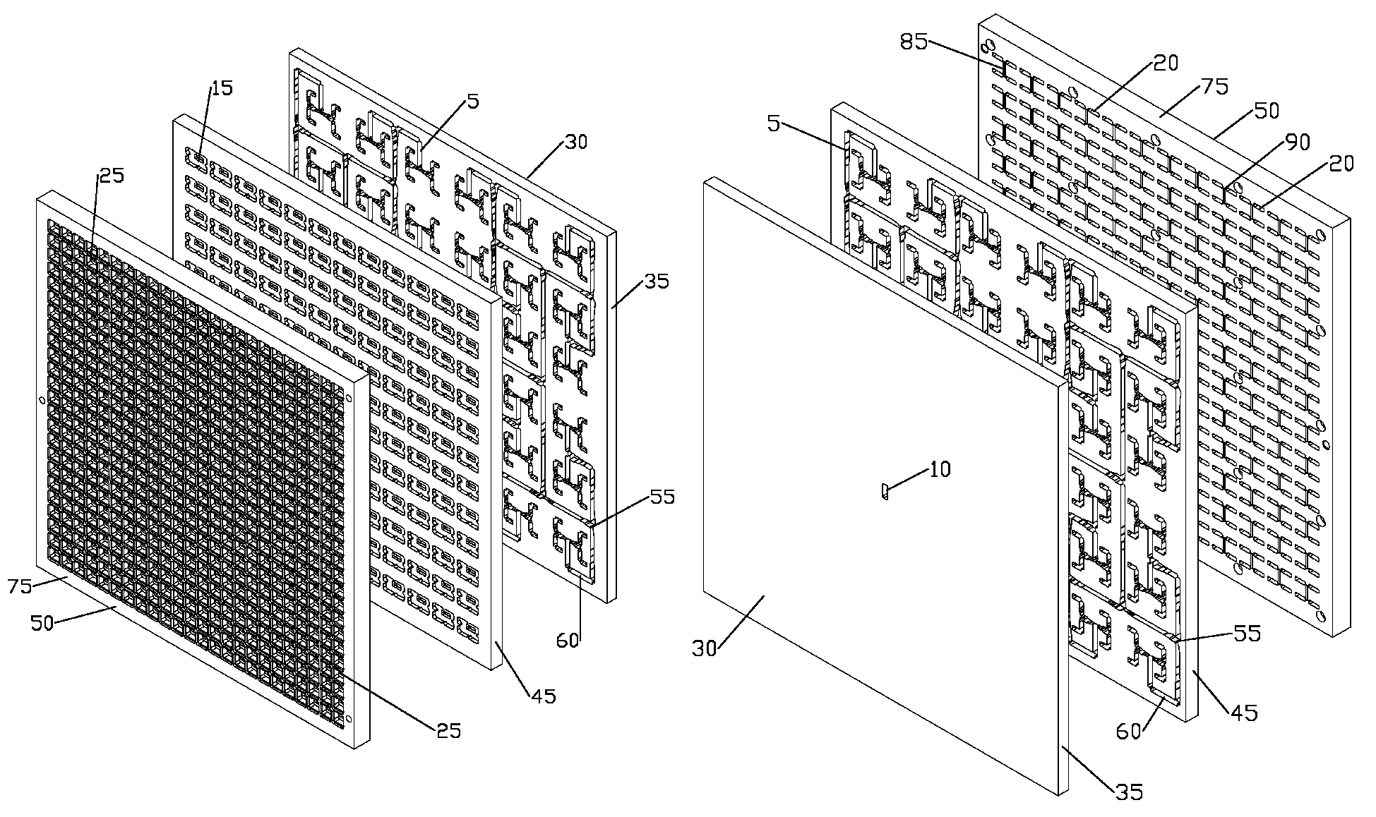
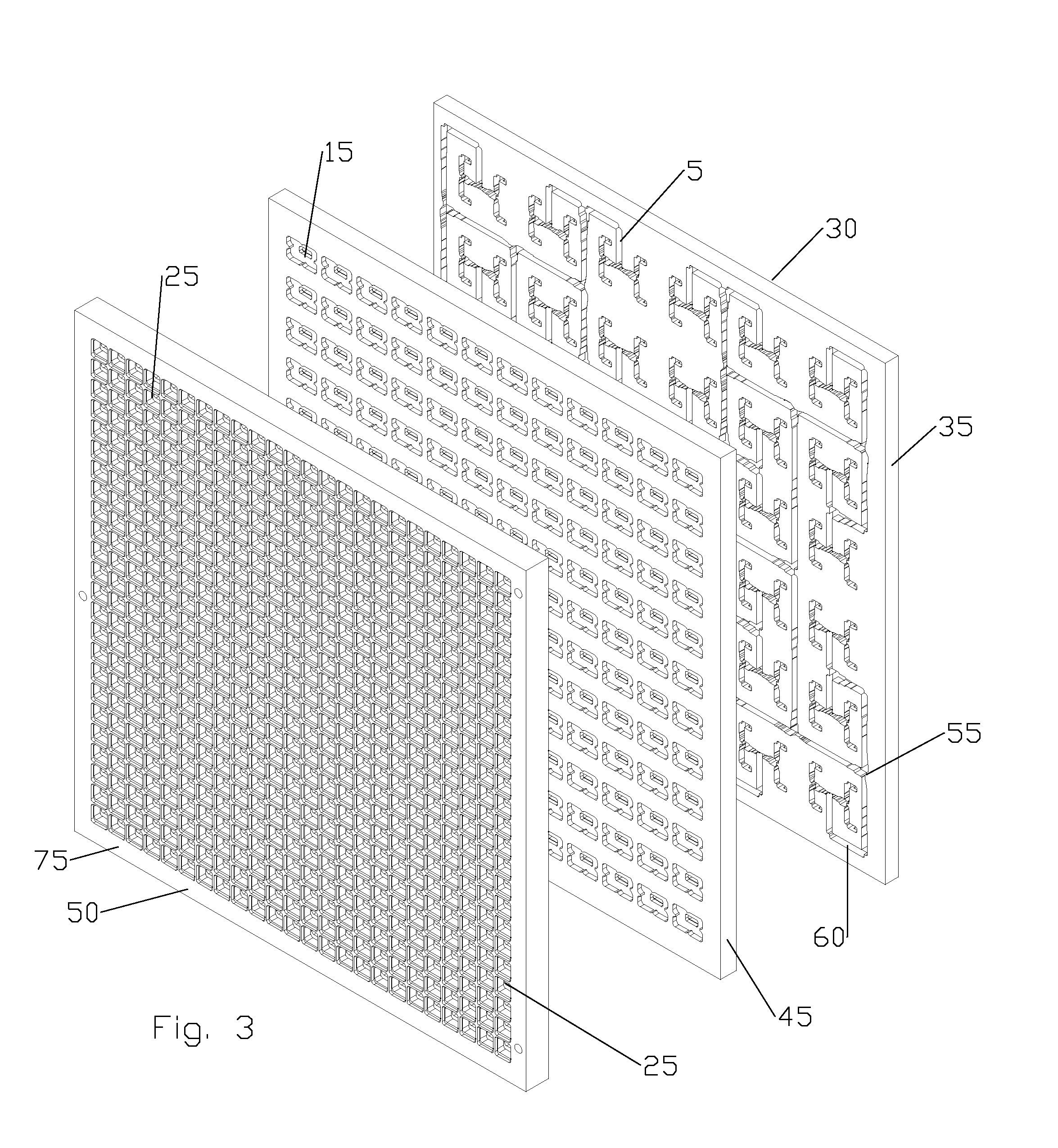
[0038]The inventors have developed a flat panel antenna utilizing a corporate waveguide network and cavity couplers provided in stacked layers. The low loss 4-way coupling of each cavity coupler significantly simplifies the requirements of the corporate waveguide network, enabling higher feed horn density for improved electrical performance. The layered configuration enables cost efficient precision mass production.
[0052]Where the desired rotation angle is 45 degrees with respect to the polarization at the input feed 10, the flat panel antenna 1 may be then mounted in a “diamond” orientation, rather than “square” orientation (with respect to the azimuth axis) and benefit from improved signal patterns, particularly with respect to horizontal or vertical polarization as the diamond orientation maximizes the number of horn radiators along each of these axes while using the advantages of the array factor.
[0054]Further simplification of the waveguide network 5 may be obtained by applying additional layers of coupling cavities. For example, instead of being coupled directly to the output ports 20, each of the primary coupling cavities 15 may feed intermediate ports 110 coupled to secondary coupling cavities 115 again each with four output ports 20, each of the output ports 20 coupled to a horn radiator 25. Thereby, the horn radiator 25 concentration may be increased by a further factor of 4 and the paired primary and secondary coupling cavities 15, 115 result in −12 dB coupling (−6 dB / coupling cavity), comparable to an equivalent corporate waveguide network, but which significantly reduces the need for extensive high density waveguide layout gyrations required to provide equivalent electrical lengths between the input feed 10 and each output port 20.
[0058]The array of horn radiators25 on the second side 50 of the output layer 75 improves directivity (gain), with gain increasing with element aperture until element aperture increases past one wavelength and grating lobes begin to be introduced. One skilled in the art will appreciate that because each of the horn radiators 20 is individually coupled in phase to the input feed 10, the prior low density ½ wavelength output slot spacing typically applied to follow propagation peaks within a common feed waveguide slot configuration has been eliminated, allowing closer horn radiator 20 spacing and thus higher overall antenna gain.
[0060]One skilled in the art will appreciate that the simplified geometry of the coupling cavities and corresponding reduction of the waveguide network requirements enables significant simplification of the required layer surface features which reduces overall manufacturing complexity. For example, the input, first intermediate, second intermediate (if present), slot (if present) and output layers 35,45,120,100,75 may be formed cost effectively with high precision in high volumes via injection molding and / or die-casting technology. Where injection molding with a polymer material is used to form the layers, a conductive surface may be applied.
[0063]From the foregoing, it will be apparent that the present invention brings to the art a high performance flat panel antenna with reduced cross section that is strong, lightweight and may be repeatedly cost efficiently manufactured with a very high level of precision.

Problems solved by technology

However, the extensive structure of a reflector dish and associated feed may require significantly enhanced support structure to withstand wind loads, which may increase overall costs.
Resonant configurations typically cannot achieve the requisite electromagnetic characteristics over the bandwidths utilized in the terrestrial point-to-point market sector, whilst travelling wave arrays typically provide a mainbeam radiation pattern which moves in angular position with frequency.
Because terrestrial point to point communications generally operate with Go / Return channels spaced over different parts of the frequency band being utilized, movement of the mainbeam with respect to frequency may prevent simultaneous efficient alignment of the link for both channels.
However, it may be necessary to select an element spacing which is generally less than one wavelength, in order to avoid the generation of secondary beams known as grating lobes, which do not respect regulatory requirements, and detract from the antenna efficiency.
Thereby, the feed network requirements may be a limiting factor of space efficient corporate fed flat panel arrays.

Method used


Image

  • Flat panel array antenna
  • Flat panel array antenna
  • Flat panel array antenna

Examples


Embodiment Construction

[0038]The inventors have developed a flat panel antenna utilizing a corporate waveguide network and cavity couplers provided in stacked layers. The low loss 4-way coupling of each cavity coupler significantly simplifies the requirements of the corporate waveguide network, enabling higher feed horn density for improved electrical performance. The layered configuration enables cost efficient precision mass production.

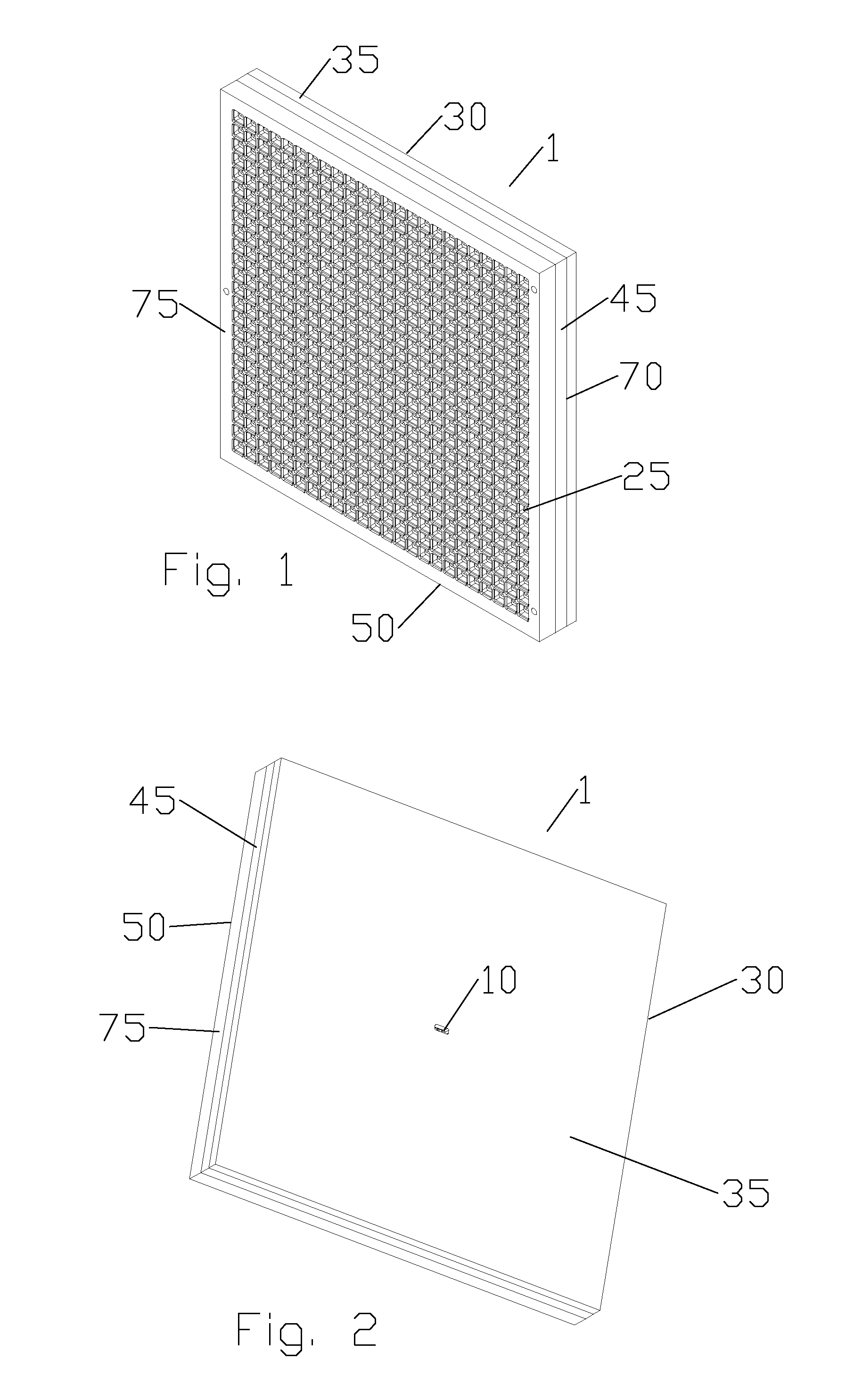
[0039]As shown in FIGS. 1-8, a first embodiment of a flat panel array antenna 1 is formed from several layers each with surface contours and apertures combining to form a feed horn array 4 and RF path comprising a series of enclosed coupling cavities and interconnecting waveguides when the layers are stacked upon one another.

[0040]The RF path comprises a waveguide network 5 coupling an input feed 10 to a plurality of primary coupling cavities 15. Each of the primary coupling cavities 15 is provided with four output ports 20, each of the output ports 20 coupled to a horn r...


PUM

PropertyMeasurementUnit
angleaaaaaaaaaa
operating frequenciesaaaaaaaaaa
rotation angleaaaaaaaaaa

Abstract

A panel array antenna has a waveguide network coupling an input feed to a plurality of primary coupling cavities. Each of the primary coupling cavities is provided with four output ports, each of the output ports coupled to a horn radiator. The waveguide network is provided on a second side of an input layer and a first side of a first intermediate layer. The primary coupling cavities are provided on a second side of the first intermediate layer and the output ports provided on a first side of an output layer, each of the output ports in communication with one of the horn radiators. The horn radiators are provided as an array of horn radiators on a second side of the output layer. Additional layers, such as a second intermediate layer and / or slot layer, may also be applied, for example to further simplify the waveguide network and / or rotate the polarization.

Description

BACKGROUND[0001]1. Field of the Invention[0002]This invention relates to a microwave antenna. More particularly, the invention provides a flat panel array antenna utilizing cavity coupling to simplify corporate feed network requirements.[0003]2. Description of Related Art[0004]Flat panel array antenna technology has not been extensively applied within the licensed commercial microwave point to point or point to multipoint market, where more stringent electromagnetic radiation envelope characteristics consistent with efficient spectrum management are common. Antenna solutions derived from traditional reflector antenna configurations such as prime focus fed axi-symmetric geometries provide high levels of antenna directivity and gain at relatively low cost. However, the extensive structure of a reflector dish and associated feed may require significantly enhanced support structure to withstand wind loads, which may increase overall costs. Further, the increased size of reflector antenn...

Claims


Application Information

Patent Timeline
Patent Type & Authority Patents(United States)
IPC IPC(8): H01Q13/00
CPCH01Q21/0075H01Q21/064Y10T29/49016
Inventor THOMSON, ALEXANDER PBIANCOTTO, CLAUDIOHILLS, CHRISTOPHER D
Owner COMMSCOPE TECH LLC
Why Eureka
Try Eureka