Fiber grating distributed strain sensor and strain monitoring method thereof

A technology of distributed strain and optical fiber grating, which is applied in the direction of using optical devices to transmit sensing components, transmission monitoring/testing/fault measurement systems, cladding optical fibers, etc., and can solve difficult to realize networking, complex demodulation algorithms, system structure Complicated problems, to achieve high spatial resolution positioning and improve measurement accuracy

Active Publication Date: 2011-05-11
杭州光学精密机械研究所
View PDF6 Cites 44 Cited by
  • Summary
  • Abstract
  • Description
  • Claims
  • Application Information

AI Technical Summary

Problems solved by technology

This system has a complex structure and requires complex demod

Method used


Image

  • Fiber grating distributed strain sensor and strain monitoring method thereof
  • Fiber grating distributed strain sensor and strain monitoring method thereof
  • Fiber grating distributed strain sensor and strain monitoring method thereof

Examples


Example Embodiment

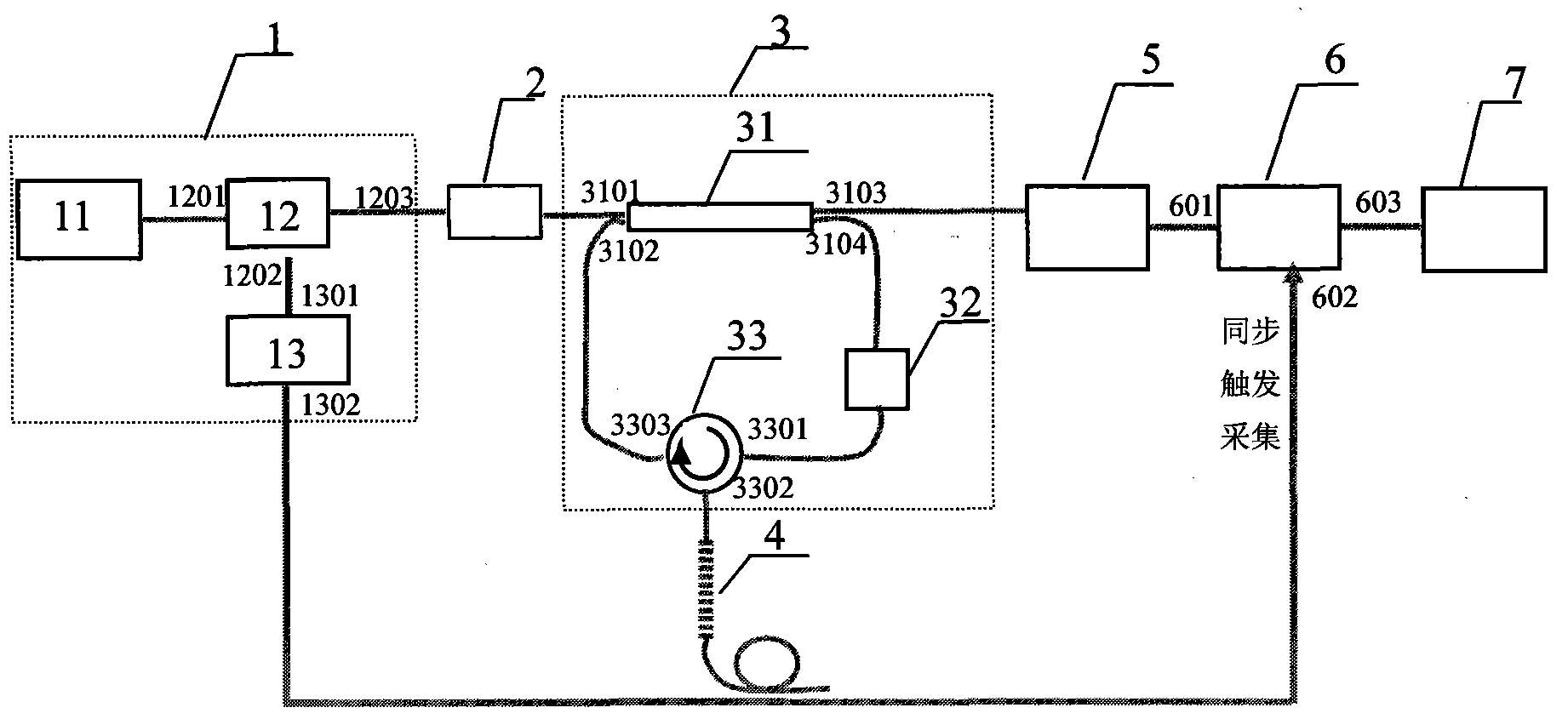
[0083] Embodiment 2, the networking system scheme based on wavelength division multiplexing is as follows Figure 4 Shown: where 1 is the light source module, using figure 1 The tunable laser 11 used in the structure is formed by connecting the acousto-optic modulator 12 and the radio frequency modulator 13 to output an optical pulse sequence. 2 is an optical connector. 3 for figure 1 Fiber optic ring in the structure. 411, 412, 413, 414...41r are cascaded fiber grating sequences connected to the ring-down cavity through the circulator 33. figure 1 The fiber grating sensing unit 4 in the structure is the same, and the other fiber gratings are sequentially cascaded and welded behind the 411 fiber grating. Through this structure, distributed strain sensing within the grating area of ​​multiple fiber gratings can be realized. The distributed strain demodulation method in the grating area of ​​each fiber grating is exactly the same as the process in the above-mentioned experimen...

Example Embodiment

[0086] Embodiment 3, a networking system scheme based on wavelength division multiplexing and time division multiplexing, such as Figure 5 Shown: where 1 is the light source module, and Figure 4 The light source used in the structure is the same. 31, 32, ..., 3j is like figure 1 The fiber optic ring formed in the structure. 411, 412, ... 41r; 421, 422, ... 42r; ...; 4j1, 4j2, ..., 4jr are the cascaded fiber grating sequence groups connected to the fiber ring 31, 32 ... 3j respectively, each level The construction method of connected fiber grating sequence is the same as Figure 4 The construction method in the WDM structure is the same. Each fiber ring and the corresponding cascaded fiber grating sequence constitute a measurement channel, 2 is the s-channel light switch, the number of light switches can reach 16 or even 32 channels, and the light switch is used to select one channel at a time. Which one needs to be measured? The strain distribution of a cascaded fiber grati...

Example Embodiment

[0088] Example 4, Image 6 It is one of the performance optimization schemes of the network system structure, in the basic structure of distributed sensing figure 1 And networking structure Figure 4 On the basis of adding a filter denoising function module, it mainly draws the access scheme of the filter denoising function module, and the other parts not shown are consistent with the aforementioned scheme. A filter fiber grating 8 is connected through the second optical circulator 34 in the ring-down cavity. Along the transmission direction of the light pulse in the ring-down cavity, the second optical circulator 34 is connected after the first fiber circulator 33. The filter fiber grating 8 is fixed on the stress tuning or temperature tuning device, and is connected to the tunable laser 11 through the automatic synchronization trigger device 9 to keep the output wavelength of the light source consistent with the central reflection wavelength of the filter fiber grating 8 to r...


PUM


Abstract

The invention relates to a fiber grating distributed strain sensor and a strain monitoring method thereof, which are characterized in that an erbium-doped fiber amplifier is added into an optical fiber fading cavity to form an active fading cavity, and an optical pulse fading sequence is obtained, so the positioning accuracy of submillimeter-magnitude spatial length measurement can be realized; and a wavelength of a tunable laser is in one-to-one correspondence with positioning data of fiber grating bragg reflection space by taking a linear chirped fiber grating or a uniform fiber grating as a sensing device, and the corresponding local strain capacity is demodulated by positioning the variable quantity of a local bragg reflection wavelength to realize distributed strain sensing. In the fiber grating distributed strain sensor, the spatial resolution ratio is improved to a submillimeter magnitude by a direct time domain measurement method, and the fiber grating distributed strain sensor has a compact structure and simple algorithm, can perform on-line monitor in real time and can be used for networking, so that the fiber grating distributed strain sensor has the large application space in the field of optical fiber sensing.

Description

technical field [0001] The invention relates to an optical fiber distributed sensor, in particular to an optical fiber grating distributed strain sensor based on optical fiber ring-down cavity technology and a strain monitoring method thereof. Background technique [0002] Optical fiber sensors have many advantages such as strong anti-electromagnetic interference, high sensitivity, good electrical insulation, safety and reliability, corrosion resistance, and can form an optical fiber sensor network, so they have broad applications in various fields such as industry, agriculture, biomedicine, and national defense. Application prospects. [0003] There are currently several technical solutions for fiber optic strain sensors, including Fiber Bragg Grating (Fiber Bragg Grating, FBG), Long Period Grating (Long Period Grating, LPG), Mach-Zehnder Interferometer (MZ-I) , fiber optic Sagnac ring, etc. The strain sensor based on fiber grating has the characteristics of high sensitiv...

Claims


Application Information

Patent Timeline
IPC IPC(8): G01D5/353G02B6/02G02B6/26H04B10/08H04B10/07
Inventor 甘久林郝蕴琦叶青潘政清蔡海文瞿荣辉方祖捷
Owner 杭州光学精密机械研究所
Why Eureka
Try Eureka