Heating cooker and tray therefor

a technology for heating cookers and trays, which is applied in the field of heating cookers, can solve the problems of unfavorable food product heating between the upper and lower sides, too much time and effort in cooking, and upsizing the heating chamber, so as to reduce the number of implements to use, prevent upsizing, and reduce cooking time and effort.

Inactive Publication Date: 2011-10-25
SHARP KK
View PDF20 Cites 15 Cited by
  • Summary
  • Abstract
  • Description
  • Claims
  • Application Information

AI Technical Summary

Benefits of technology

[0008]Accordingly, an object of the present invention is to provide a heating cooker which is capable of reducing the number of implements to use depending on the content of cooking, reducing the time and effort of cooking, preventing upsizing, and preventing uneven heating, and also to provide a heating cooker tray which makes it possible to evenly heat both upper and lower sides of an object to be cooked with less time and effort without using auxiliary tools such as grill netting.

Problems solved by technology

However in the conventional heating cooker, the lower heater is blocked from the food product by the turntable and bottom plate, so that heat is not conducted smoothly from the lower heater to the food product, thereby causing a problem of uneven heating of the food product between the upper side and the lower side.
Thus, there are many instruments to use, which causes a problem of too much time and effort in cooking.
Moreover, the heating chamber needs to house grill netting and a square plate in addition to the turntable, which causes a problem of upsizing of the heating chamber.
Further, it is necessary to clean the grill netting after cooking, which causes a problem of too much time and effort in maintenance.
Moreover, when an object to be cooked is cooked through heating from only the upper side, the object to be cooked is directly placed on the turntable, so that grill netting becomes unnecessary and will be placed out of the heating cooker.
Therefore, it becomes necessary to secure a space to place the grill netting out of the heating cooker, thereby causing a problem in which the grill netting placed out of the heating cooker becomes obstructive and gives an untidy impression.

Method used


Image

  • Heating cooker and tray therefor
  • Heating cooker and tray therefor
  • Heating cooker and tray therefor

Examples


Embodiment Construction

[0048]Herein below, the present invention will be described in details in conjunction with the embodiments with reference to the drawings.

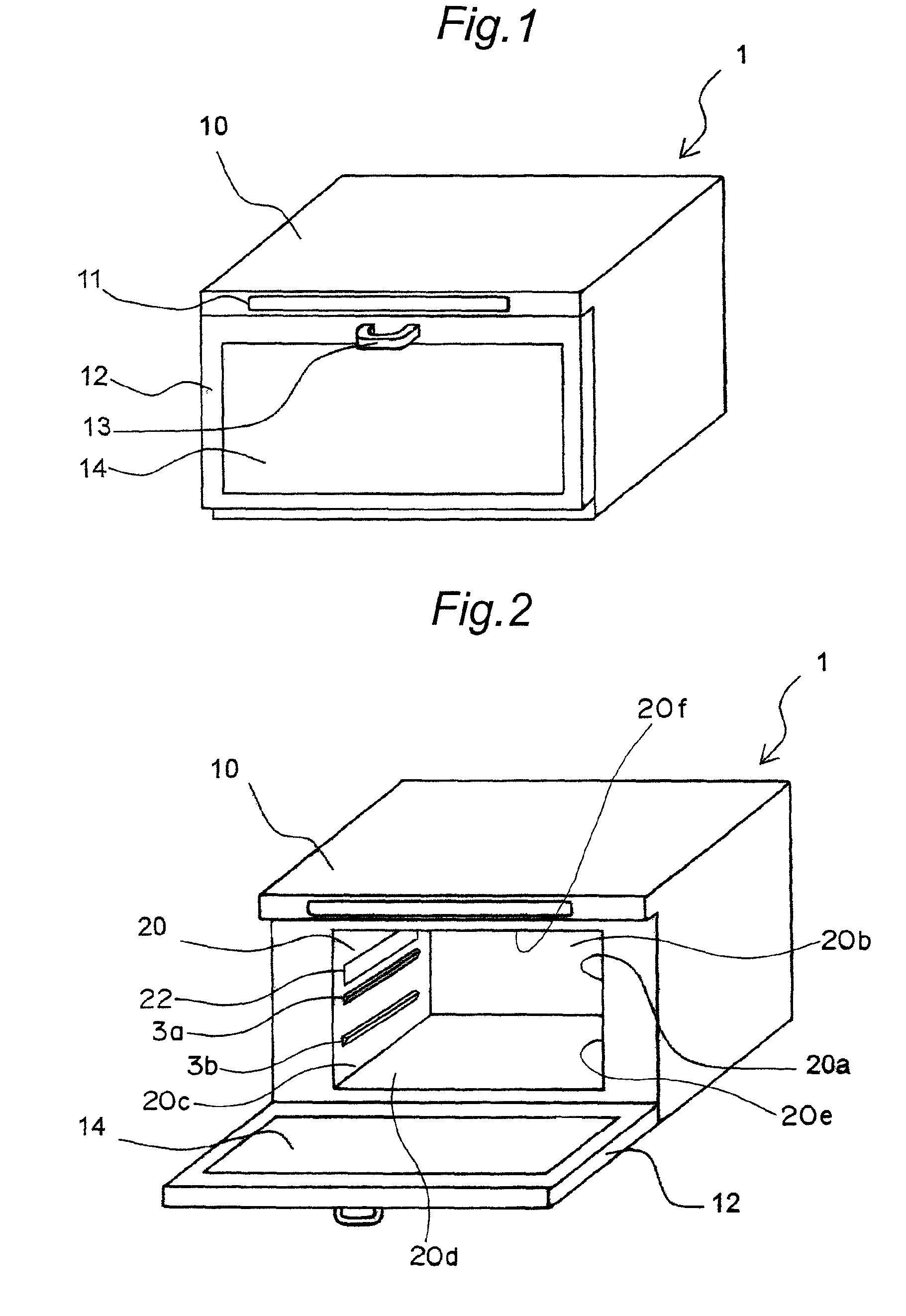
[0049]FIG. 1 is a perspective view showing an external appearance of a heating cooker in the present embodiment. The heating cooker 1 is structured such that an operation panel 11 is provided on the upper side of the front surface of a cabinet 10 with a rectangular parallelepiped shape and a door 12 rotating around a lower end side is provided on the lower side of the operation panel 11 on the front surface of the cabinet 10. A handle 13 is provided on the upper side of the door 12 and a window 14 made of heat-resistant glass is fitted into the door 12.

[0050]FIG. 2 is a perspective view showing an external appearance of the heating cooker 1 in the state where the door 12 is opened. In the cabinet 10, a heating chamber 20 with a rectangular parallelepiped shape is provided. The heating chamber 20 includes an opening 20a to be opened and closed by t...


PUM


Abstract

A heating cooker has a side wall of a heating chamber (20) formed with an outlet (22) for discharging a heating fluid and an engagement portion (3a). A tray (4) has an edge portion (4a), a side wall portion (4b) having a thorough hole (4f), a flat surface portion (4c), an inner wall portion (4d), and a bottom portion (4e). When the tray is engaged with the engagement portion with its front surface side facing up, the through hole faces the outlet. A part of the discharged heating fluid is fed to the rear surface side of the tray through the through hole, and the remaining fluid is fed to the front surface side. When the tray is engaged with the engagement portion with its rear surface side facing up, an opening in a groove portion (4i) defined between the side wall portion and the inner wall portion faces upward.

Description

BACKGROUND OF THE INVENTION[0001]1. Field of the Invention[0002]The present invention relates to a heating cooker which heats an object to be cooked with heating fluid, and a heating cooker tray which is placed in a heating chamber of the heating cooker to support the object to be cooked.[0003]2. Description of the Related Art[0004]One of the conventional heating cookers which heat objects to be cooked includes an upper heater provided on the ceiling of a heating chamber and a lower heater provided on the rear side of a bottom plate of the heating chamber, in which a food product is placed on a turntable provided on the bottom plate in the heating chamber so as to be cooked with the upper and lower heaters (see, e.g., JP H2-306030 A).[0005]However in the conventional heating cooker, the lower heater is blocked from the food product by the turntable and bottom plate, so that heat is not conducted smoothly from the lower heater to the food product, thereby causing a problem of uneven ...

Claims


Application Information

Patent Timeline
Patent Type & Authority Patents(United States)
IPC IPC(8): A21B1/22F24C1/00H05B3/00
CPCA21B3/04F24C15/16F24C15/2007
Inventor UEDA, SHINYAYAMAGUCHI, KIYOSHIMATSUBAYASHI, KAZUYUKI
Owner SHARP KK
Why Eureka
Try Eureka