
Light assemblies

a technology of light assembly and lens, which is applied in the field of light assembly, can solve the problems of black mask around the lens, change in air flow inside the light assembly, and reduce the effective light effect, so as to reduce the weight of the lens, reduce the moving mass of the light deflecting means, and be convenient to us

Active Publication Date: 2011-10-25
MARTIN PROFESSIONAL
View PDF11 Cites 2 Cited by
  • Summary
  • Abstract
  • Description
  • Claims
  • Application Information

AI Technical Summary

Benefits of technology

The invention is a light assembly with a variable spread angle, which can be achieved by a light deflecting means. The light deflecting means can be mechanically fixed in relation to the housing of the light assembly, which ensures constant control of the air flowing around the optical components. The front lens can be designed with a central part that has optical properties different from the surrounding parts, allowing for a soft change in the light beam when the light deflecting means is moved between the first and second position. The light assembly can be used in a moving head fixture on stage or in a floodlight. The light deflecting means can be positioned between the first and second position by a first actuator. The front lens can have a central part with optical properties that differ from the surrounding parts, allowing for a wide-angle or narrow-angle light beam depending on the position of the light deflecting means. The light deflecting means can be a fresnel lens or a general aspherical lens. The light assembly can be designed with a closed volume, reducing the dirt collected on the optical components. The light assembly can be controlled by computer means.

Problems solved by technology

A black mask around the lenses reduces the effective light effect by converting the light into heat.
Movement of a front lens, a lamp or a reflector can lead to a change in the air flow inside the light assembly.
Movement of the front lens can lead to a change of the air flow in the light assembly.

Method used


Image

  • Light assemblies
  • Light assemblies
  • Light assemblies

Examples


Embodiment Construction

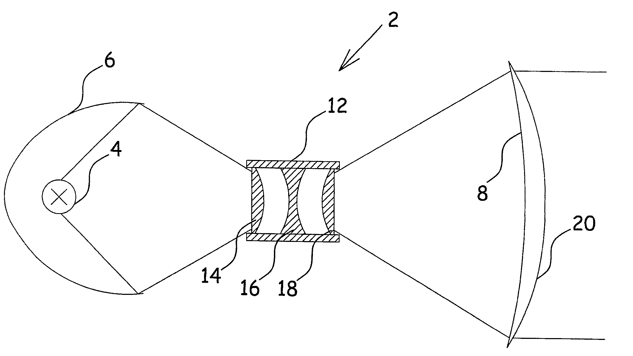
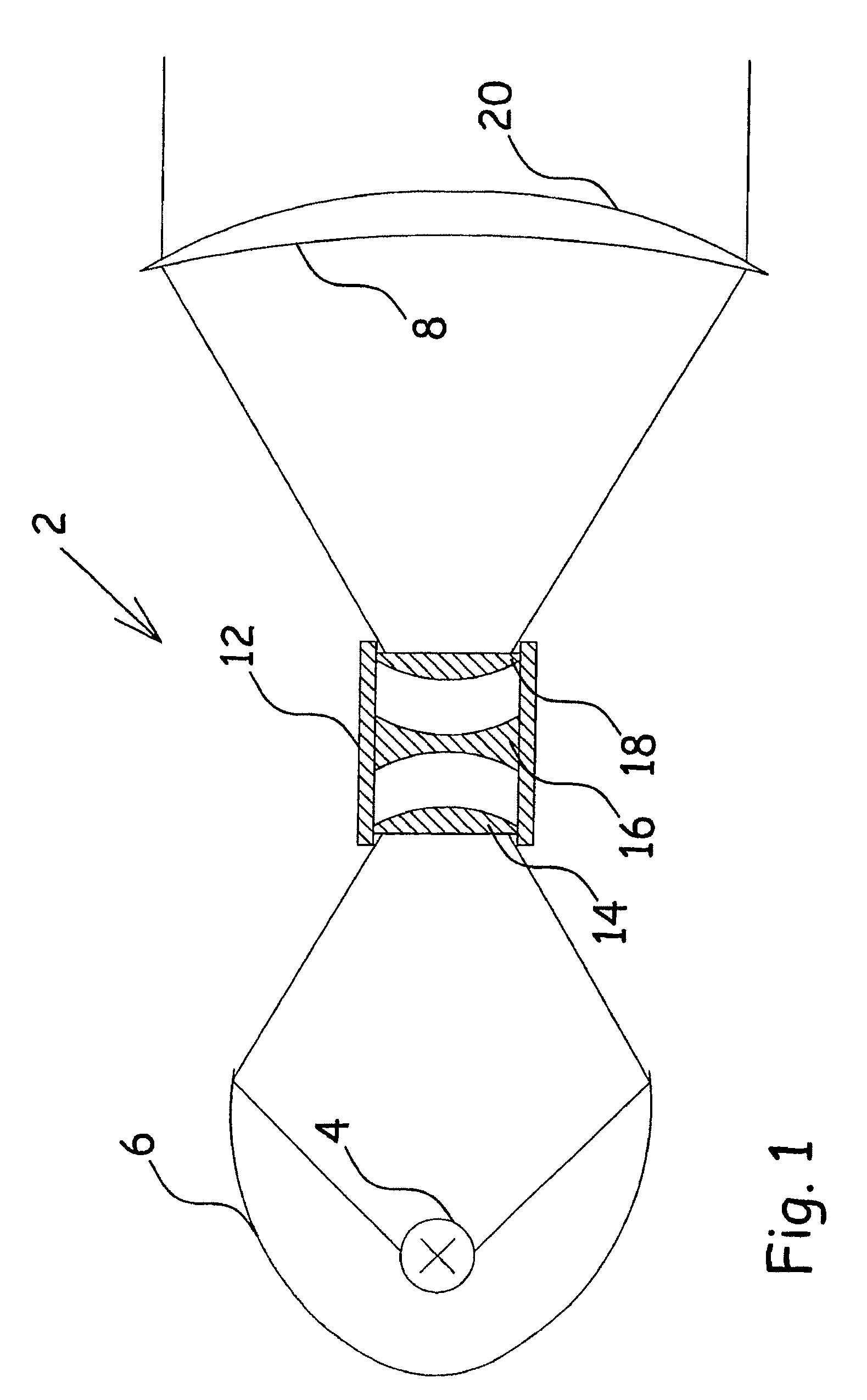
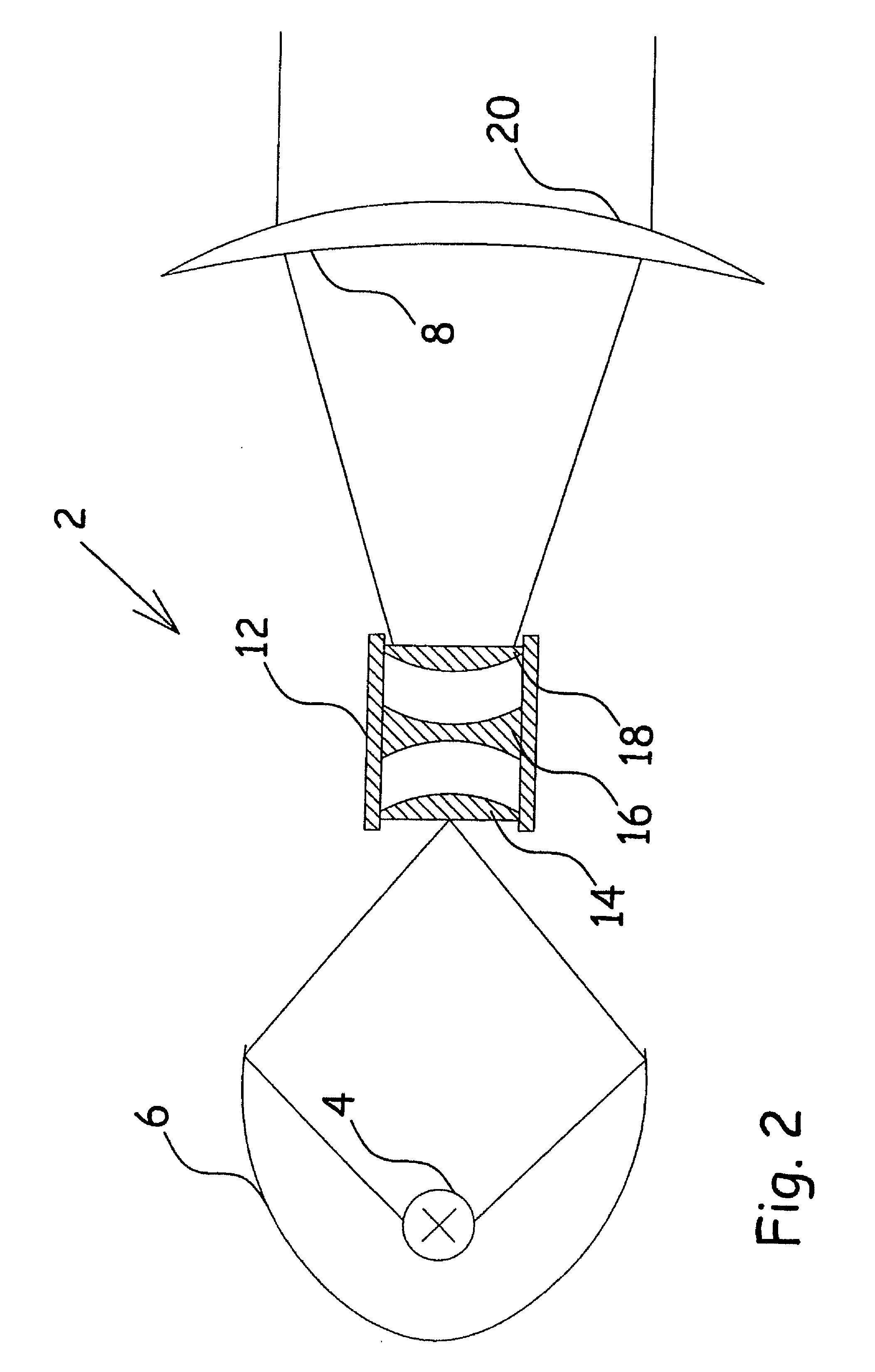
[0007]This can be achieved by a light assembly as described in the opening paragraph if the light deflecting means in a first position concentrates the light beam into the central part of the front lens to generate a wide-angle light beam, where the light deflecting means in a second position distributes the light beam over essential the entire front lens to generate a narrow-angle light beam, where the light deflecting means is movable between the first and the second position, where the light deflecting means is able to operate in different positions between the first and second position.

[0008]Because of the internal light deflecting means, the front lens does not need to be movable. Furthermore, the reflector and the light source are held in a fixed but adjustable position. This may result in constant control of the air flowing around the optical components. The light deflecting means can operate in a closed volume. This way, the dirt collected on the surfaces of the optical comp...


PUM


Abstract

A method for forming a light beam, and a light assembly having at least one light source with a fixed reflector which directs a beam of light light assembly having a front lens, and a light deflecting mechanism for changing the light angle of the light beam after passing through the front lens. The front lens has a central part that differs from the surrounding parts of the front lens, and the light deflecting mechanism, in a first position, concentrates the light beam into the central part of the front lens to generate a wide-angle light beam, and in a second position, distributes the light beam over the entire front lens to generate a narrow angle light beam. The light deflecting mechanism is connected with a first actuator, and is movable between the first and the second position.

Description

FIELD OF THE INVENTION[0001]The present invention relates to a light assembly and a method comprising at least one light source which generates a beam of light into the light forming means and a light forming means at least comprising a light deflecting means for changing the angular and spatial distribution of the light hitting the front lens.BACKGROUND OF THE INVENTION[0002]U.S. Pat. No. 6,808,969 B2 concerns a first multiple lens array designed with positive-power lenses producing multiple bundles of converging light rays and a second multiple lens array designed with negative-power lenses producing multiple bundles of collimated light rays at a certain optimal separation between the two multiple lens arrays. As the axial separation between the two multiple lens arrays increases, the divergence of the entire beam of light increases. A black mask around the lenses reduces the effective light effect by converting the light into heat.[0003]US20050135106A1 concerns a fresnel lens spo...

Claims


Application Information

Patent Timeline
Patent Type & Authority Patents(United States)
IPC IPC(8): F21S8/00
CPCF21V5/008F21V5/048F21V14/06F21W2131/406F21V5/02F21V13/04F21Y2101/00
Inventor JOERGENSEN, DENNIS THYKJAERSOERENSEN, MARTINHYLDAHL, HEIDI MARIANNE
Owner MARTIN PROFESSIONAL
Learn More