
Turbine bucket tip shroud edge profile

a technology of tip shroud and bucket, which is applied in the direction of liquid fuel engines, vessel construction, marine propulsion, etc., can solve the problems of significant difference in fillet stress between pressure and suction sides of airfoils, negatively affecting the creep life of buckets, and high load on tip shroud fillets, so as to maximize creep life and improve stage efficiency

Active Publication Date: 2011-10-25
GENERAL ELECTRIC CO
View PDF2 Cites 11 Cited by
  • Summary
  • Abstract
  • Description
  • Claims
  • Application Information

AI Technical Summary

Benefits of technology

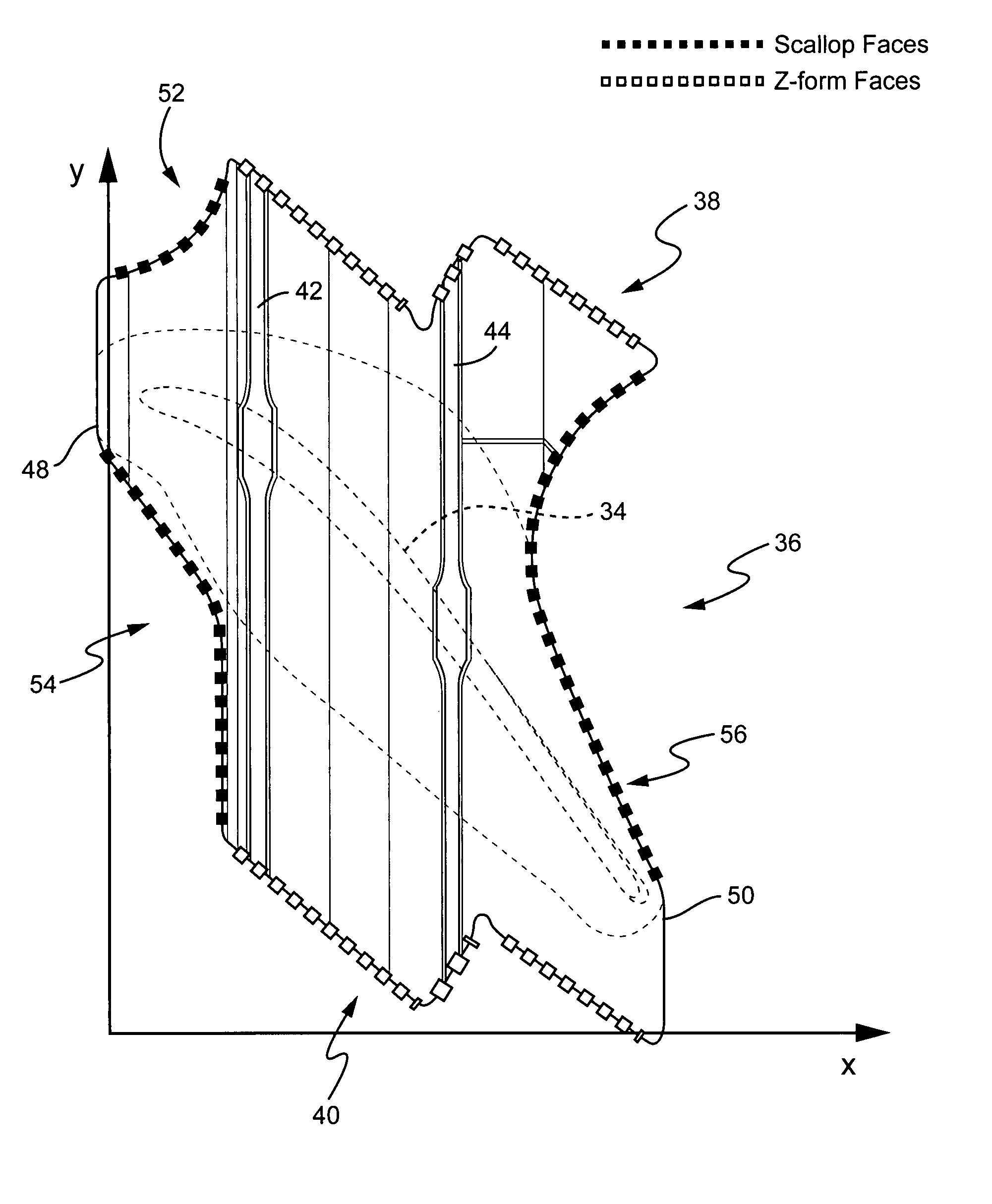
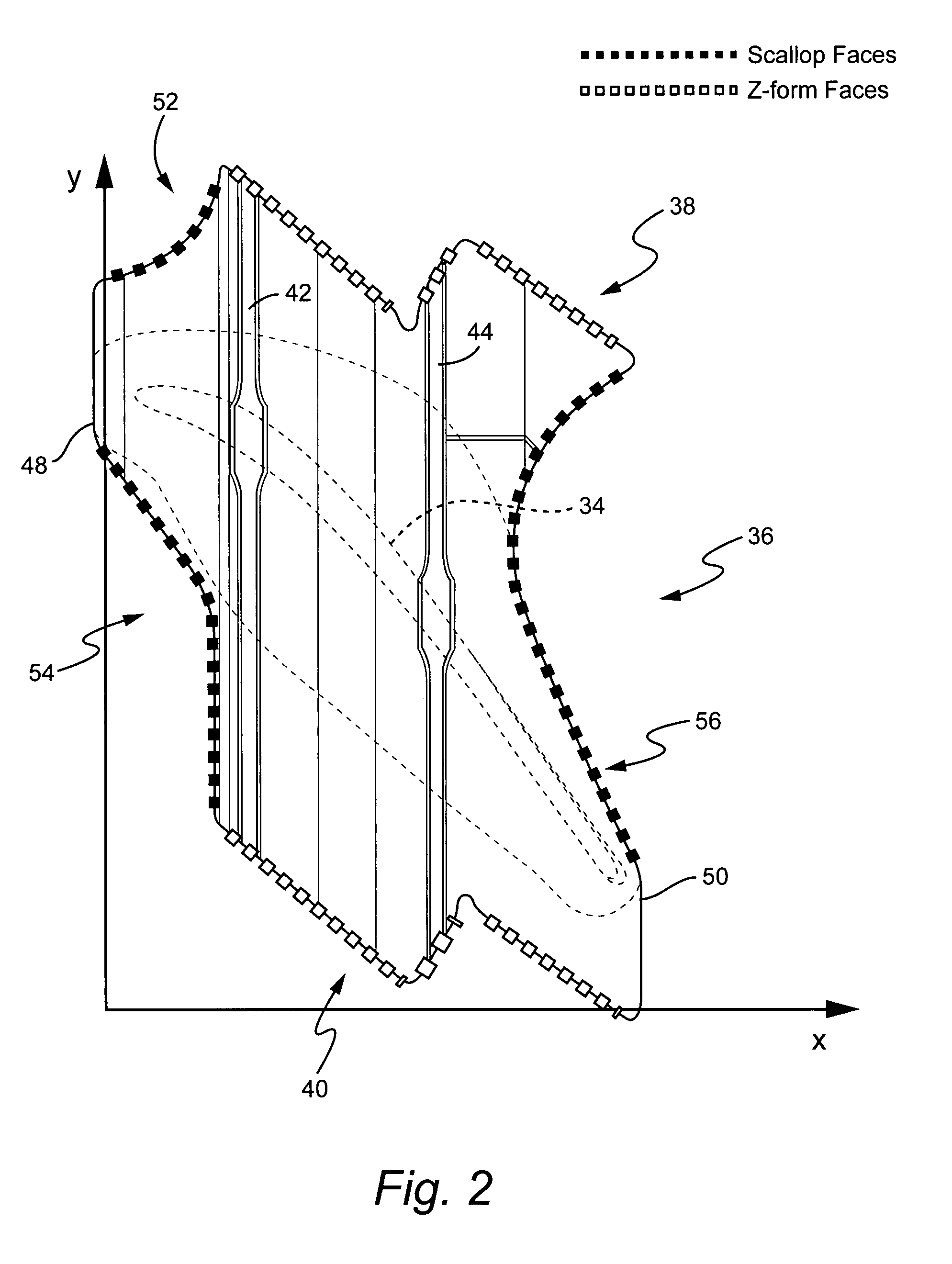
The present invention provides a turbine bucket with a tip shroud that has optimized mass distribution to balance stresses and maximize creep life. The leading edge of the tip shroud has a predetermined profile with scalloped sections in Cartesian coordinate system at points 1-6 and 7-21, while the trailing edge has a scalloped section at points 22-41. The first and second Z form edge profiles are also provided for the tip shroud. These profiles help improve the efficiency of the turbine and provide better coverage of the airfoil throat.

Problems solved by technology

Particularly, a significant difference in fillet stresses occurs between pressure and suction sides of the airfoil at its intersection with the tip shroud because of tip shroud mass imbalance relative to the airfoil.
This mass imbalance negatively impacts the creep life of the bucket.
That is, the tip shroud mass distribution in prior buckets resulted in a highly loaded tip shroud fillet and reduced creep life.
Further, certain prior tip shrouds do not cover the airfoil throat, with resultant negative impact on stage efficiency due to flow leakage over the tip shroud.

Method used


Image

  • Turbine bucket tip shroud edge profile
  • Turbine bucket tip shroud edge profile
  • Turbine bucket tip shroud edge profile

Examples


Embodiment Construction

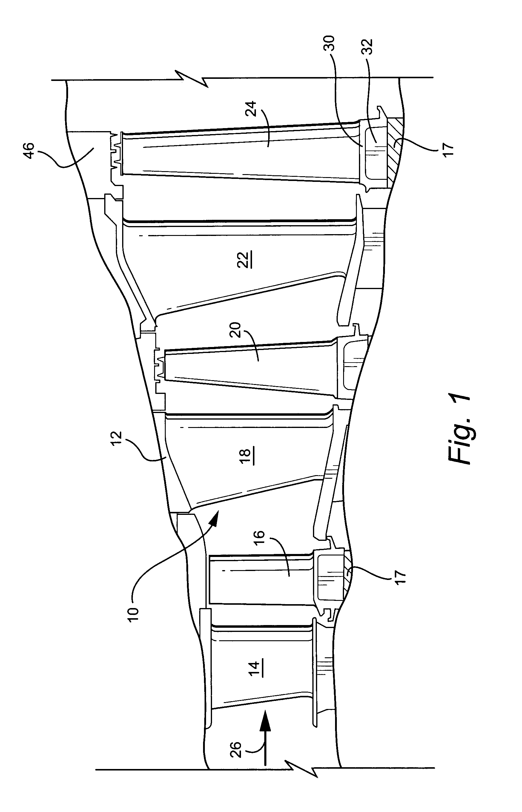
[0012]Referring now to the drawing figures, particularly to FIG. 1, there is illustrated a hot gas path, generally designated 10, of a gas turbine 12 including a plurality of turbine stages. Three stages are illustrated. For example, the first stage comprises a plurality of circumferentially spaced nozzles 14 and buckets 16. The nozzles are circumferentially spaced one from the other and fixed about the axis of the rotor. The first stage buckets 16, of course, are mounted on the turbine rotor wheel 17. A second stage of the turbine 12 is also illustrated, including a plurality of circumferentially spaced nozzles 18 and a plurality of circumferentially spaced buckets 20 mounted on the rotor. The third stage is also illustrated including a plurality of circumferentially spaced nozzles 22 and buckets 24 mounted on the rotor 17. It will be appreciated that the nozzles and buckets lie in the hot gas path 10 of the turbine 12, the direction of f low of the hot gas through the hot gas path...


PUM


Abstract

A turbine bucket includes a bucket airfoil having a tip shroud with a leading edge comprising two scalloped faces and a trailing edge comprising a third scalloped face defining leading and trailing edge profiles substantially in accordance with Cartesian coordinate values of X and Y as points 1-41 set forth in Table I. The X and Y values are distances in inches which, when respective points are connected by smooth, continuing arcs define the leading and trailing edge tip shroud scalloped profiles. The tip shroud further has first and second, upper and lower, Z form edge profiles substantially in accordance with Cartesian coordinate values of X and Y as points 42-59 and 60-77, respectively of Table II.

Description

BACKGROUND OF THE INVENTION[0001]The present invention relates to turbine buckets having an airfoil and a tip shroud carried by the airfoil. More particularly, the invention relates to leading, trailing and Z-form edge profiles of a tip shroud carried by an airfoil of a turbine bucket.[0002]Buckets for turbines typically comprise an airfoil, a platform, a shank and dovetail. The dovetail is secured in a complementary slot in a turbine wheel. Oftentimes, the airfoil includes an integrally formed tip shroud. The bucket including the airfoil and tip shroud are, of course, rotatable about the engine centerline during operation and the airfoil and the tip shroud are located in the hot gas path. Because the tip shroud is mounted at the tip of the airfoil, substantial stresses occur in the tip shroud fillet region between the tip shroud and the airfoil tip. Particularly, a significant difference in fillet stresses occurs between pressure and suction sides of the airfoil at its intersection...

Claims


Application Information

Patent Timeline
Patent Type & Authority Patents(United States)
IPC IPC(8): F01D5/22
CPCF01D5/225F05D2250/74Y02T50/673Y02T50/60
Inventor CHIURATO, TONYCHAN, SZE BUN BRIANRAICA, BOGDAN RAZVANBARUA, SAMARPERRY, II, JACOB CHARLES
Owner GENERAL ELECTRIC CO
Learn More