Inductively-coupled plasma source

a plasma source and inductive coupling technology, applied in glass making apparatus, instruments, manufacturing tools, etc., can solve the problems of reducing coupling efficiency, reducing the life of the vessel, and wasting rf power, so as to maximize gas excitation efficiency, maximize the life of the vessel, and efficiently couple energy to the plasma

Active Publication Date: 2011-06-28
MKS INSTR INC
View PDF61 Cites 53 Cited by
  • Summary
  • Abstract
  • Description
  • Claims
  • Application Information

AI Technical Summary

Benefits of technology

[0006]One discovery of the present invention is an electromagnetic configuration that can efficiently couple energy to a plasma and maximize gas excitation efficiency while maximizing the life of the vessel. In this electromagnetic configuration, plasmas can be generated in plasma vessels of relatively simple geometries by an induced electromagnetic field without introducing significant electrostatically coupling between the plasma and induction coil. The invention, in one aspect, features a substantially linear plasma vessel that can be used with varying configurations of magnetic cores to efficiently excite a gas and minimize erosion of the vessel containing the excited gas.
[0011]To maximize gas excitation in the tube, a property of the electric field can be varied along a longitudinal axis of the tube. For example, the magnitude of the induced electric field can be varied to maximize gas excitation. A property of the electric field can also be varied in the direction perpendicular to the longitudinal axis of the tube. For example, the magnitude of the induced electric field can be arranged to be higher in the center region of a plasma vessel, so that most plasma is generated in the center region, away from the walls of the plasma vessel. In some embodiments, the apparatus includes a gas inlet. In some embodiments, the gas inlet of the plasma vessel is configured to maximize gas excitation and / or stability of the plasma in the plasma vessel. The gas inlet can be configured to, for example, direct gas along an inner surface of a wall of the vessel.
[0013]Free charges can be generated to assist in ignition of the plasma in the plasma vessel in some embodiments. An electrode positioned in the plasma vessel, an electrode capacitively coupled to the plasma vessel, or an ultraviolet source optically coupled to the plasma vessel can be used to generate free charges which assist in ignition of the plasma in the plasma vessel.
[0019]In some embodiments, the method also involves supplying a gas to the plasma vessel via a gas inlet. The method can involve configuring the gas inlet to maximize stability of the plasma in the plasma vessel. In some embodiments, supplying the gas to the plasma vessel involves maximizing gas excitation in the plasma vessel. In some embodiments, supplying the gas involves directing the gas along an inner surface of a wall in the plasma vessel.
[0022]In some embodiments, the method involves protecting the plasma and magnetic core from overheating by using a thermal protection circuit with a network of thermal sensors and thermal switches.

Problems solved by technology

However, electrostatic shields often reduce coupling efficiency between an induction coil and plasma, causing RF power to be wasted and impedance matching to become more difficult.
Conventional plasma sources can be expensive and difficult to maintain.
Certain vessel shapes are more expensive and difficult to manufacture.
Further, plasma vessels are vulnerable to erosion during operation and must be replaced periodically in conventional systems.

Method used


Image

  • Inductively-coupled plasma source
  • Inductively-coupled plasma source
  • Inductively-coupled plasma source

Examples


Embodiment Construction

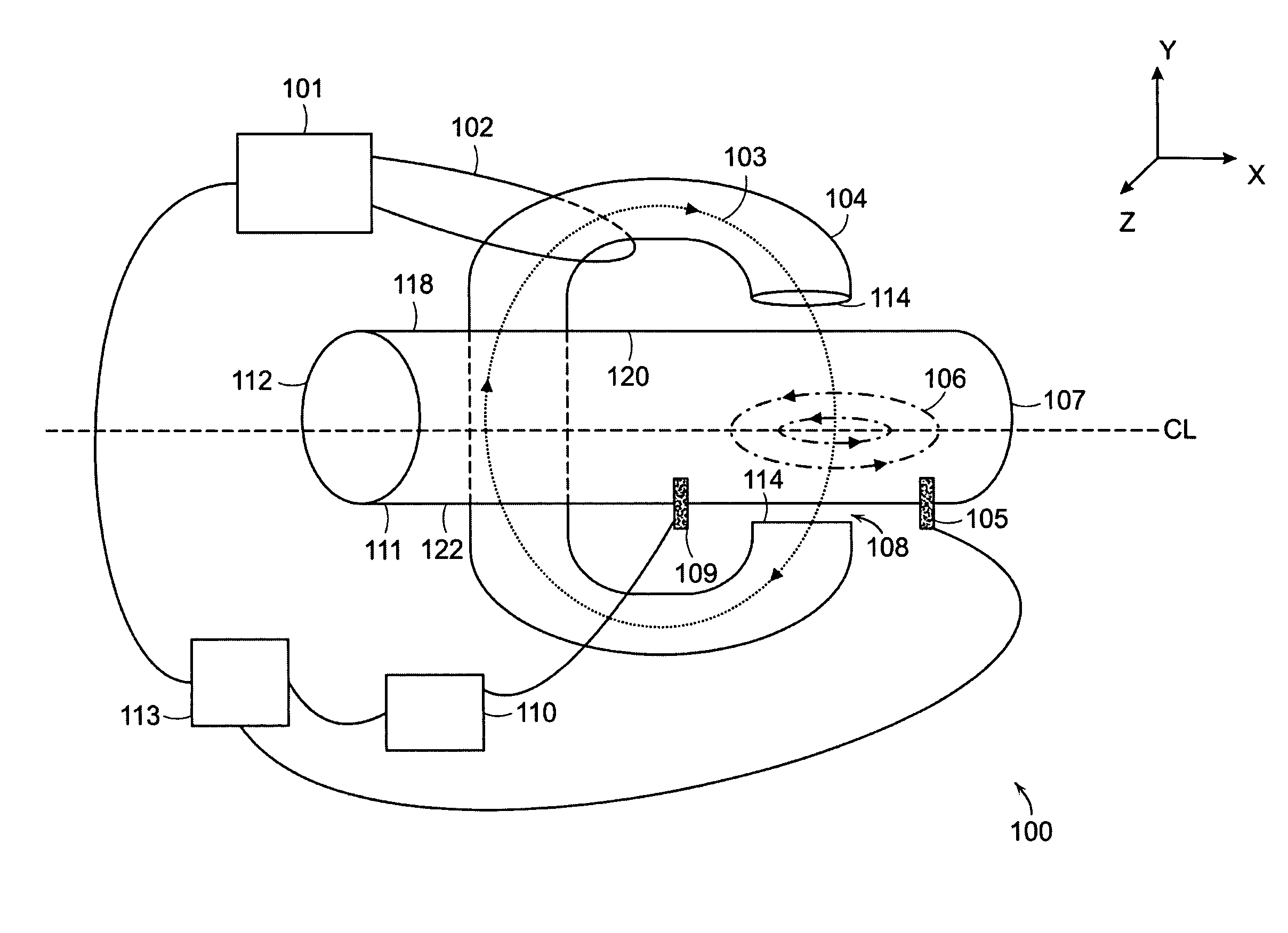
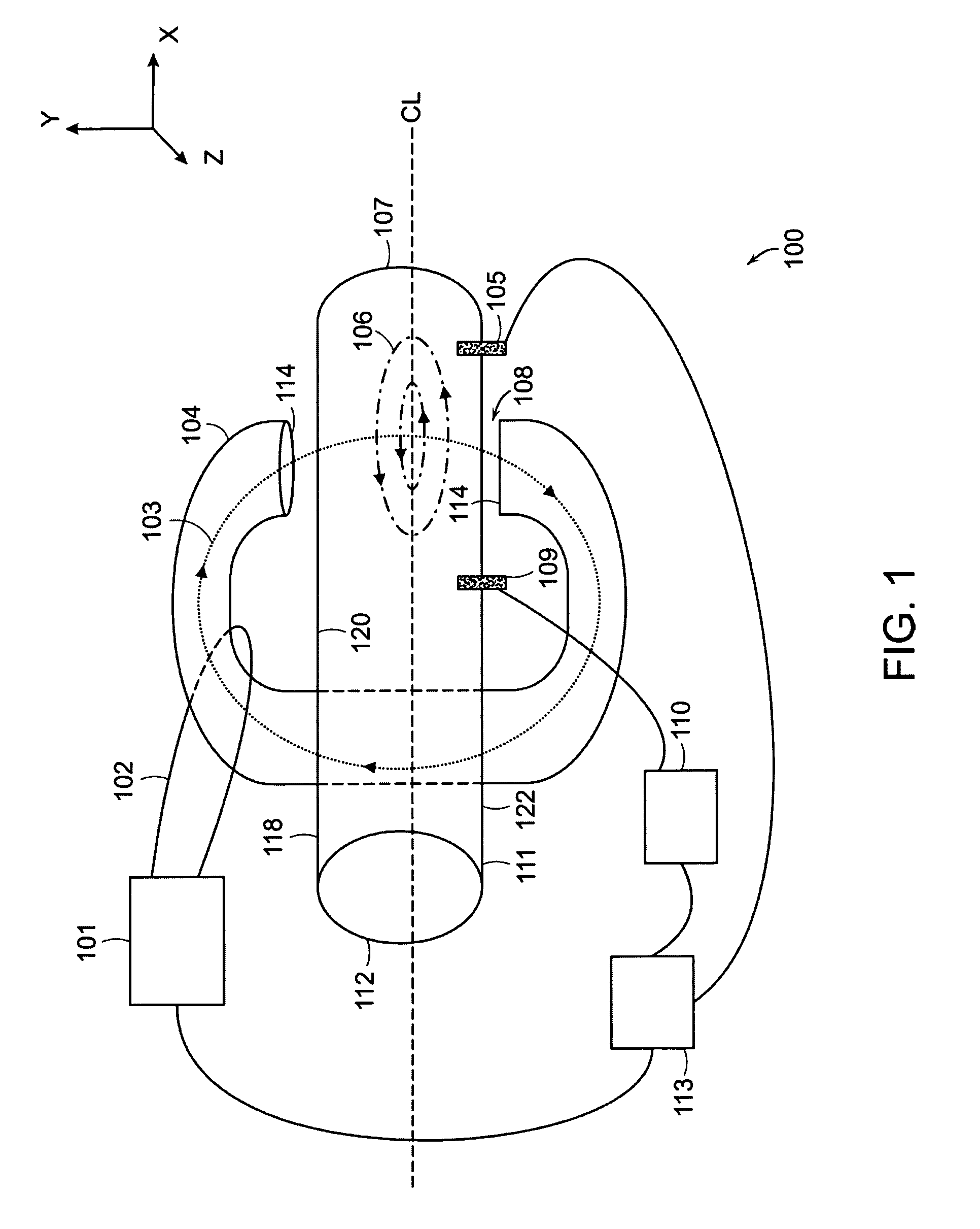
[0038]is a partial schematic view of a gas excitation system 100 that generates excited gases, according to an illustrative embodiment of the invention. Plasmas are often used to activate gases, placing them in an excited state such that the gases have an enhanced reactivity. Excitation of a gas involves elevating the energy state of the gas. In some cases, the gases are excited to produce dissociated gases containing ions, free radicals, atoms and / or molecules. The system 100 includes a plasma vessel 111 and at least one magnetic core 104 with a gap 108. The vessel 111 is located at least partially within the gap 108 of the core 104. The system 100 also includes a power supply 101 electrically coupled to a primary winding 102 that surrounds a portion of the magnetic core 104. The power supply 101 provides a flow of electric current through the winding 102 that generates an alternating magnetic field 103 through the core 104. The magnetic field 103 passes through the core 104, unidi...


PUM

PropertyMeasurementUnit
frequenciesaaaaaaaaaa
voltageaaaaaaaaaa

Abstract

A method and apparatus for exciting gas that involves generating an alternating magnetic field unidirectionally through a magnetic core defining a gap, across the gap and through a plasma vessel that includes dielectric material. The magnetic field induces an electric field in the plasma vessel that generates the plasma.

Description

FIELD OF THE INVENTION[0001]The invention relates generally to methods and apparatus for generating plasma and exciting gases. More particularly, the invention relates to apparatus and methods for generating excited gases containing ions, free radicals, atoms and molecules and apparatus for and methods of processing materials with excited gases.BACKGROUND OF THE INVENTION[0002]Plasmas are often used to activate gases placing them in an excited state causing enhanced reactivity. The gases may be excited to produce dissociated gases containing ions, free radicals, atoms and molecules. Excited gases are used for numerous industrial and scientific applications, including processing solid materials such as semiconductor wafers and powders, other gases, and liquids. The parameters of the dissociated gas and conditions under which the dissociated gas interacts with a material to be processed by the system vary widely depending on the application. For example, atomic fluorine is used to etc...

Claims


Application Information

Patent Timeline
Patent Type & Authority Patents(United States)
IPC IPC(8): H05B31/26
CPCH01J37/321H01J37/32522H05H1/46H05H1/24H01J37/3266C03B19/143C03B37/0183C03B37/01861H05H1/4652
Inventor CHEN, XING
Owner MKS INSTR INC
Why Eureka
Try Eureka