Methods and systems for analyzing the degradation and failure of mechanical systems

Inactive Publication Date: 2005-02-08
BATTELLE MEMORIAL INST
View PDF20 Cites 53 Cited by
  • Summary
  • Abstract
  • Description
  • Claims
  • Application Information

AI Technical Summary

Benefits of technology

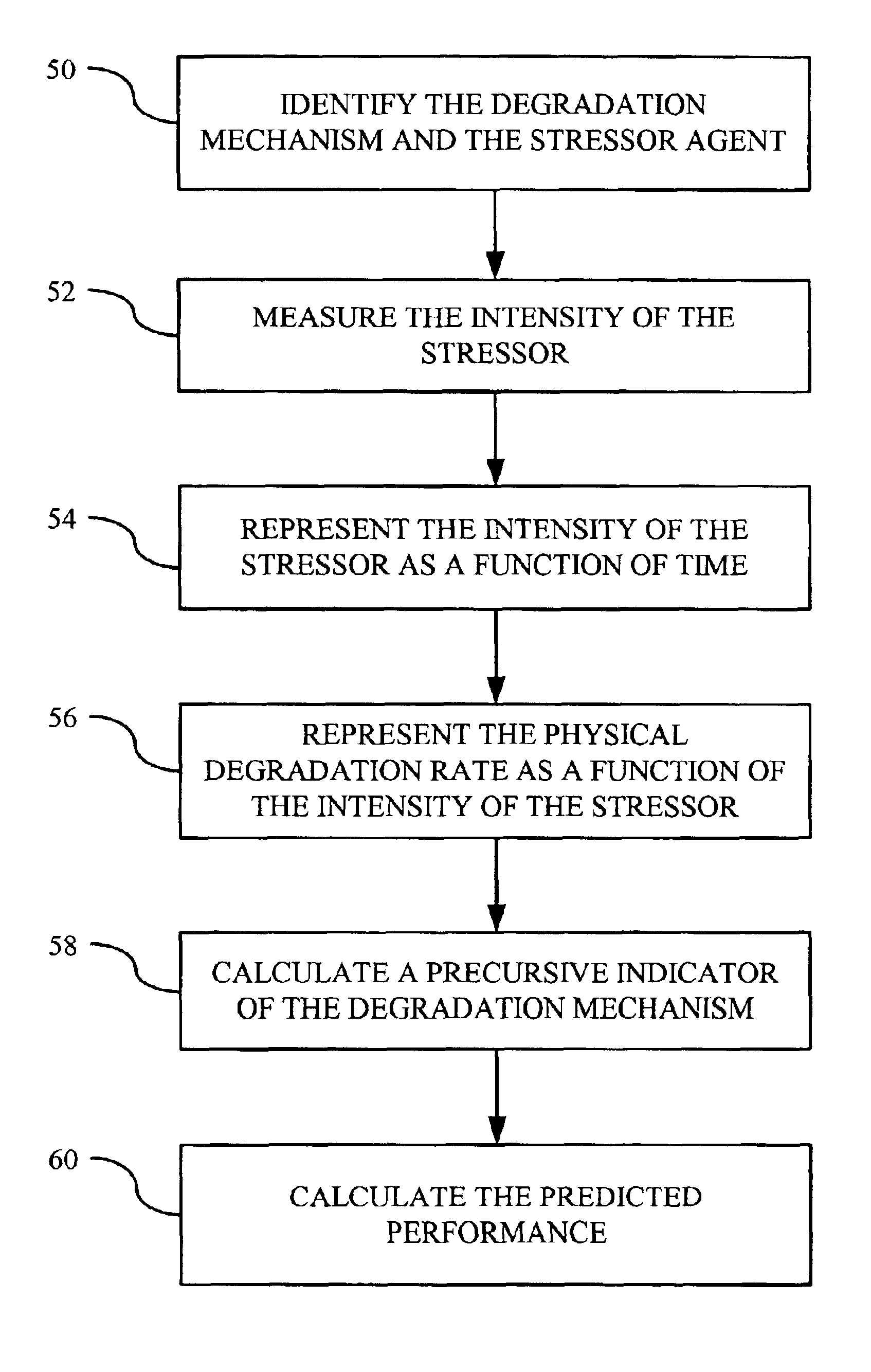
Methods and systems for analyzing the degradation and failure of mechanical systems are provided. In general, the methods and systems focus on measuring and quantifying stressors that are responsible for the activation of degradation mechanisms in the machine component of interest. The intensity of the stressor may be correlated with the rate of physical degradation according to some determinable function such that a derivative relationship exists between the

Problems solved by technology

Machine failure has been a major concern of industrial operators for well over a century.
Machine failure typically results from a degradation mechanism inherent in the operation of the machine (e.g., vibration, erosion, corrosion, cavitation, etc.).
Ultimately, this degradation mechanism causes the machine to fail, thereby requiring replacement or repair of the machine or its components.
Because machine repair often creates significant economic losses (in terms of both actual repair costs and lost operating time), machine operators desire to minimize the frequency at which machine components fail while also minimizing the cost of operation.
Therefore, corrective maintenance is reactive in nature, and little, if any, attention is paid to ensuring that the operating conditions are within the design envelope.
Consequently, the life span of the equipment is typically below the estimates of the manufacturer.
For example, erosion or cavitation in a pump can shorten the life expectancy of the pump by an order of magnitude or more.
However, in critical applications, such as the safety systems of a nuclear power plant, this r

Method used


Image

  • Methods and systems for analyzing the degradation and failure of mechanical systems
  • Methods and systems for analyzing the degradation and failure of mechanical systems
  • Methods and systems for analyzing the degradation and failure of mechanical systems

Examples


first embodiment

One of the most predominant degradation mechanisms resulting in centrifugal pump failure is vibration. Other mechanisms and causes, however, may also lead to the failure of the pump (e.g., erosion, corrosion, etc.). One of the principal stressor agents that contribute to vibration in the centrifugal pump is the misalignment of the axial or angular plane of rotation of the driving shaft with the driven shafts or an imbalanced or axial-eccentricity condition in one of the rotating elements.

FIG. 6 shows a centrifugal pump 100 utilizing a dynamic laser alignment system that may be used to measure alignment and vibration. As seen in FIG. 6, a motor 102 includes a driving shaft 104 that couples with an impeller shaft 106 of the pump 100. The impeller shaft 106 of the pump 100 is coupled to an impeller, or rotor, (not shown) whose rotating blades force liquid entering the pump at input 108 through a volute, or scroll, (not shown) to output 110. The coupling may be any type of suitable coup...

second embodiment

The second representative embodiment involves quantifying the vibration of the pump-motor system by measuring the reaction forces exerted by the drive shaft 104 on the bearings of the motor 102 using a system of load cells. FIG. 9 shows one possible embodiment of the load cell system, but is not intended to be limiting in any way. Instead, a number of different load cell configurations are possible, including the use of only one set of load cells on either the inboard or outboard side of the motor 102, or the use of a set of load cells elsewhere on the rotating shafts of the pump-motor system.

FIG. 9 shows the motor 102 and its armature 150. Two motor shafts extend from the motor armature 150—an inboard motor shaft 152 and an outboard motor shaft 154. The inboard motor shaft 152 is housed and rotates within an inboard radial bearing 156. Similarly, the outboard motor shaft 154 is housed and rotates within an outboard radial bearing 158. As more fully discussed below, each of the radi...

third embodiment

Another one of the predominant degradation mechanisms resulting in centrifugal pump failure is cavitation. Cavitation in a centrifugal pump is recognized as a fluid state in close proximity to, or above, the working fluid saturation line (i.e., how close the fluid is in terms of temperature / pressure space to the boiling point of the liquid). The principal stressor agent that contributes to cavitation in the centrifugal pump is flow throttling and suction temperature rise.

FIG. 13 shows the centrifugal pump 100 and a set of acoustic emission sensors 200. In particular, FIG. 13 shows the volute 202 of the pump 100 as it extends from the rotor 204 toward the output 110. Acoustic emission sensors 200 are placed along the exterior of the volute 202 and on the exterior adjacent the eye of the impeller 206. The acoustic emission sensors 200 may comprise any suitable acoustic sensor. In one specific embodiment, for instance, the acoustic emission sensors 200 comprise PINDUCER VP-1093 acousti...


PUM


Abstract

Methods and systems for identifying, understanding, and predicting the degradation and failure of mechanical systems are disclosed. The methods include measuring and quantifying stressors that are responsible for the activation of degradation mechanisms in the machine component of interest. The intensity of the stressor may be correlated with the rate of physical degradation according to some determinable function such that a derivative relationship exists between the machine performance, degradation, and the underlying stressor. The derivative relationship may be used to make diagnostic and prognostic calculations concerning the performance and projected life of the machine. These calculations may be performed in real time to allow the machine operator to quickly adjust the operational parameters of the machinery in order to help minimize or eliminate the effects of the degradation mechanism, thereby prolonging the life of the machine. Various systems implementing the methods are also disclosed.

Description

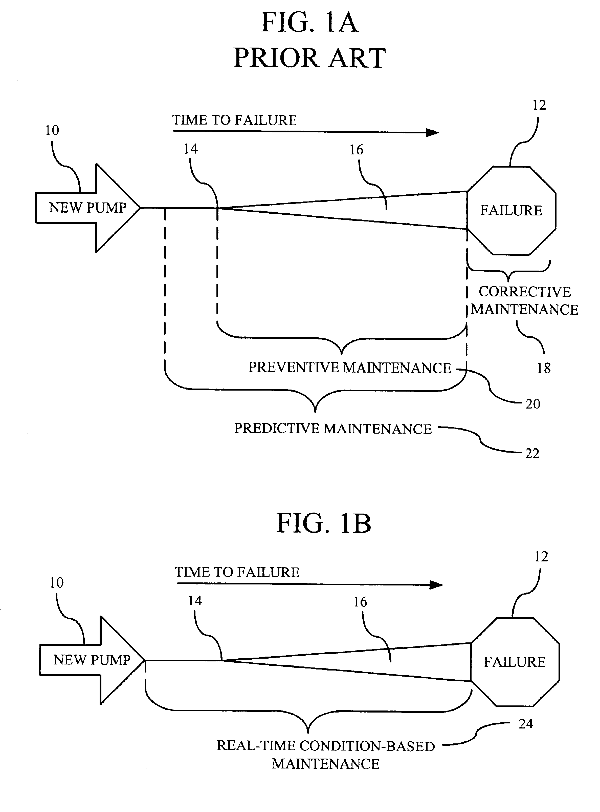
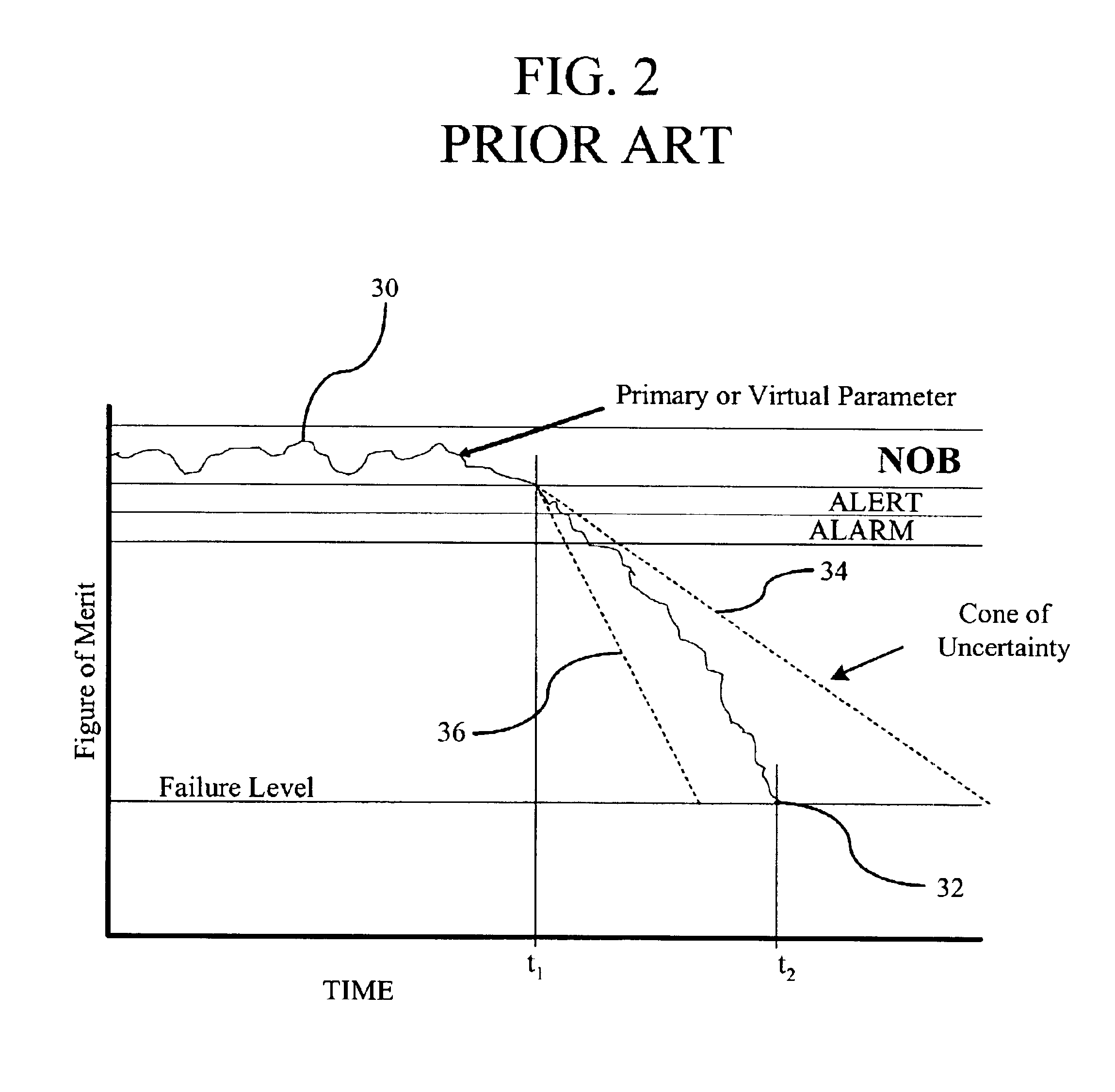
FIELDThis application relates to machine diagnostics and prognostics.BACKGROUNDMachine failure has been a major concern of industrial operators for well over a century. Machine failure typically results from a degradation mechanism inherent in the operation of the machine (e.g., vibration, erosion, corrosion, cavitation, etc.). Ultimately, this degradation mechanism causes the machine to fail, thereby requiring replacement or repair of the machine or its components. Because machine repair often creates significant economic losses (in terms of both actual repair costs and lost operating time), machine operators desire to minimize the frequency at which machine components fail while also minimizing the cost of operation. To minimize the operation and maintenance costs, a number of different maintenance regimes may be employed.A first, and most basic, maintenance regime is corrective maintenance. Corrective maintenance involves running a piece of machinery until it fails. Therefore, co...

Claims


Application Information

Patent Timeline
IPC IPC(8): G05B23/02
CPCG05B23/0283G05B23/0221
Inventor JARRELL, DONALD B.SISK, DANIEL R.HATLEY, DARREL D.KIRIHARA, LESLIE J.PETERS, TIMOTHY J.
Owner BATTELLE MEMORIAL INST
Why Eureka
Try Eureka