Turbine bucket tip shroud edge profile

a technology of tip shroud and bucket, which is applied in the direction of liquid fuel engines, vessel construction, marine propulsion, etc., can solve the problems of affecting the creep life of the bucket. , to achieve the effect of improving stage efficiency and maximizing creep li

Inactive Publication Date: 2005-05-17
GENERAL ELECTRIC CO
View PDF8 Cites 54 Cited by
  • Summary
  • Abstract
  • Description
  • Claims
  • Application Information

AI Technical Summary

Benefits of technology

[0003]In accordance with a preferred embodiment of the present invention, there is provided a bucket tip shroud having leading and trailing edge profiles for optimizing tip shroud mass distribution to balance tip shroud fillet stresses, thereby maximizing creep life and also ensuring coverage of the airfoil throat to improve stage efficiency. Particularly, the leading edge of the tip shroud, i.e., the edge generally facing axially upstream in the hot gas path of the turbine, has a predetermined profile substantially in accordance with X and Y coordinate values in a Cartesian coordinate system at points 12-20 set forth in Table I, which follows, where X and Y are distances in inches from an origin. When points 12-20 are connected by smooth, continuing arcs, the points define the leading edge tip shroud profile. Similarly, the tip shroud trailing edge has a predetermined profile substantially in accordance with X and Y values of the coordinate system at points 1-11 set forth in Table I, wherein X and Y are distances in inches from the origin. When points 1-11 are connected by smooth, continuing arcs, these points define the trailing edge tip shroud profile.
[0004]Further, the leading and trailing edge profiles are matched to the airfoil profile at 95% span to maximize tip shroud creep life and improve stage efficiency. Particularly, the bucket airfoil has an airfoil profile at 95% span, i.e., just radially inwardly of the fillet region at the intersection of the tip shroud and the tip of the airfoil. This airfoil profile section at 95% span is defined, in accordance with X, Y coordinate values set forth in Table II, which follows, wherein the X and Y coordinate values of Table II are in inches and have the same origin as the X, Y coordinate values of Table I. Hence, the mass distribution of the tip shroud defined by the leading and trailing edge profiles is located relative to the airfoil section tip at 95% span.
[0005]It will also be appreciated that as the airfoil section and tip shroud heats up in use, the leading and trailing edge profiles of the tip shrouds will change as a result of stress and temperature. Thus, the cold or room temperature profile for the tip shroud is given by the X and Y coordinates for manufacturing purposes. Because a manufactured tip shroud may be different from the nominal tip shroud profile given by Table I, a distance of ±0.080 inches from the nominal profile at each of the leading and trailing edges in a direction normal to any surface location along the nominal profile and which includes any coating, defines a leading and trailing edge profile envelope for the tip shroud. The tip shroud is robust to this variation without impairment of mechanical and aerodynamic functions.

Problems solved by technology

Particularly, a significant difference in fillet stresses occurs between pressure and suction sides of the airfoil at its intersection with the tip shroud because of tip shroud mass imbalance relative to the airfoil.
This mass imbalance negatively impacts the creep life of the bucket.
That is, the tip shroud mass distribution in prior buckets resulted in a highly loaded tip shroud fillet and reduced creep life.
Further, certain prior tip shrouds do not cover the airfoil throat, with resultant negative impact on stage efficiency due to flow leakage over the tip shroud.

Method used


Image

  • Turbine bucket tip shroud edge profile
  • Turbine bucket tip shroud edge profile
  • Turbine bucket tip shroud edge profile

Examples


Embodiment Construction

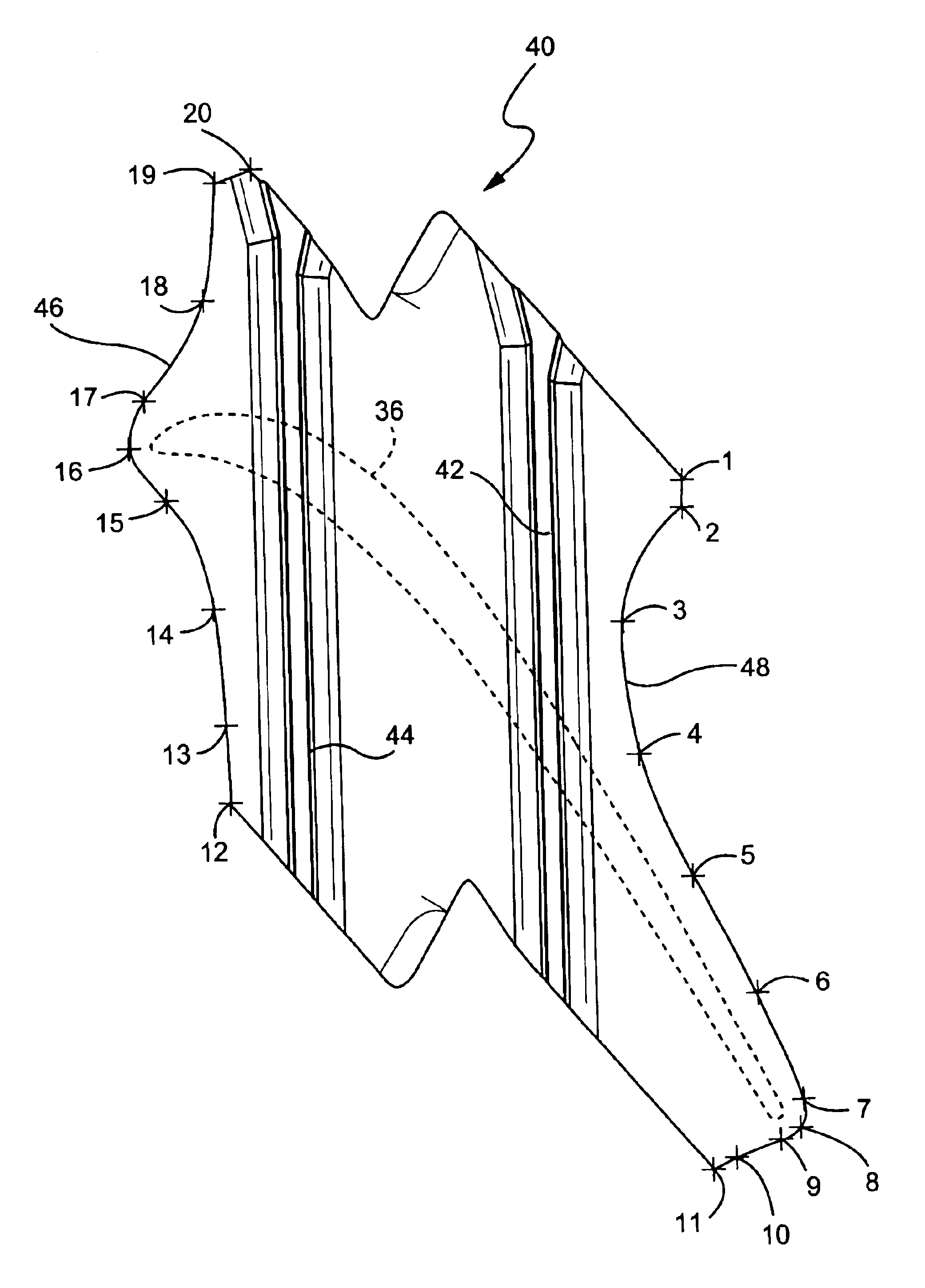
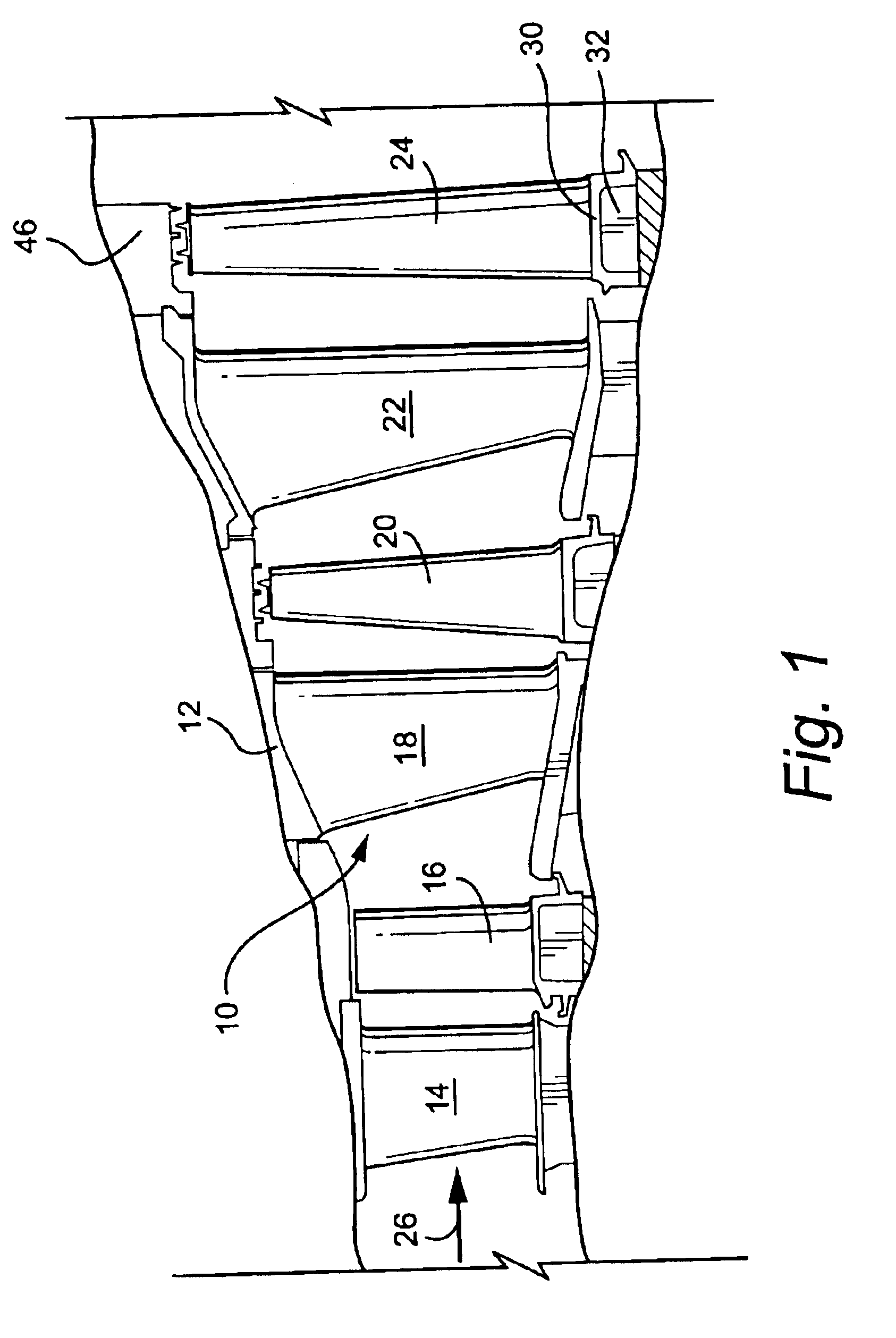
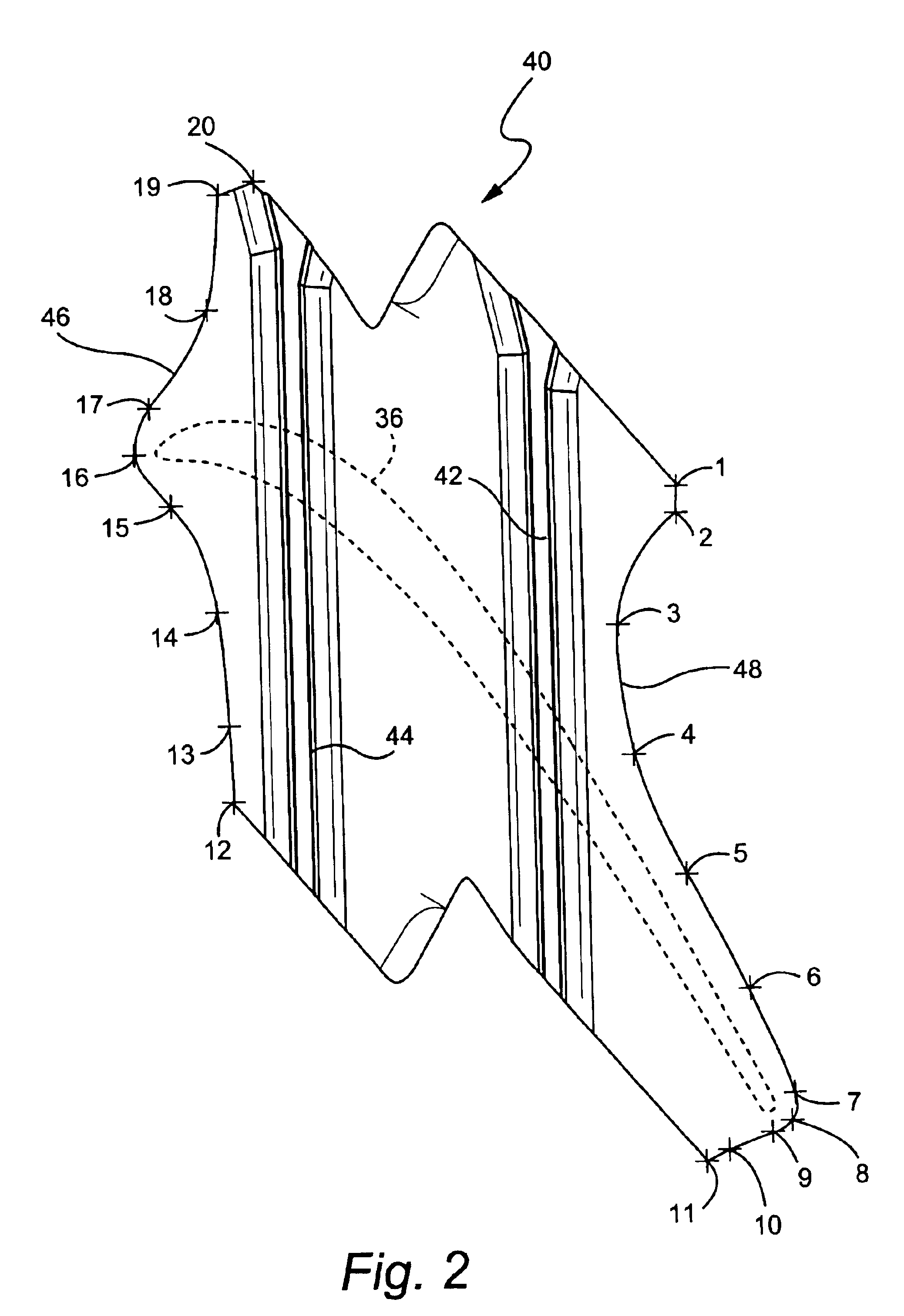
[0013]Referring now to the drawing figures, particularly to FIG. 1, there is illustrated a hot gas path, generally designated 10, of a gas turbine 12 including a plurality of turbine stages. Three stages are illustrated. For example, the first stage comprises a plurality of circumferentially spaced nozzles 14 and buckets 16. The nozzles are circumferentially spaced one from the other and fixed about the axis of the rotor. The first stage buckets 16, of course, are mounted on the turbine rotor wheel, not shown. A second stage of the turbine 12 is also illustrated, including a plurality of circumferentially spaced nozzles 18 and a plurality of circumferentially spaced buckets 20 mounted on the rotor. The third stage is also illustrated including a plurality of circumferentially spaced nozzles 22 and buckets 24 mounted on the rotor. It will be appreciated that the nozzles and buckets lie in the hot gas path 10 of the turbine 12, the direction of flow of the hot gas through the hot gas ...


PUM


Abstract

A turbine bucket includes a bucket airfoil having a tip shroud with leading and trailing edges defining leading and trailing edge profiles substantially in accordance with Cartesian coordinate values of X and Y at points 12-20 and 1-11, respectively, set forth in Table I. The X and Y values are distances in inches which, when respective points 12-20 and 1-11 are connected by smooth, continuing arcs, define the leading and trailing edge tip shroud profiles. An airfoil profile at 95% span is defined by Cartesian coordinate values of X, Y and Z in Table II having the same X, Y origin along the radial Z axis as the origin of Table I. The profiled leading and trailing edges of the tip shroud relative to the airfoil profile afford optimum tip shroud mass distribution which maximizes creep life of the bucket. Stage efficiency is also improved by providing a tip shroud covering the airfoil throat.

Description

BACKGROUND OF THE INVENTION[0001]The present invention relates to turbine buckets having an airfoil and a tip shroud carried by the airfoil and particularly relates to leading and trailing edge profiles of a tip shroud carried by an airfoil of a turbine bucket.[0002]Buckets for turbines typically comprise an airfoil, a platform, a shank and dovetail. The dovetail is secured in a complementary slot in a turbine wheel. Oftentimes, the airfoil includes an integrally formed tip shroud. The bucket including the airfoil and tip shroud are, of course, rotatable about the engine centerline during operation and the airfoil and the tip shroud are located in the hot gas path. Because the tip shroud is mounted at the tip of the airfoil, substantial stresses occur in the tip shroud fillet region between the tip shroud and the airfoil tip. Particularly, a significant difference in fillet stresses occurs between pressure and suction sides of the airfoil at its intersection with the tip shroud beca...

Claims


Application Information

Patent Timeline
Patent Type & Authority Patents(United States)
IPC IPC(8): F01D5/14F01D5/20F01D5/22
CPCF01D5/225F05D2250/70
Inventor SNOOK, DANIEL DAVIDCLEVELAND, PETER GAINES
Owner GENERAL ELECTRIC CO
Why Eureka
Try Eureka