Implant with attached element and method of making such an implant

a technology of attached elements and implants, which is applied in the field of implants, can solve problems such as the difficulty of aligning markers with stents, and achieve the effects of precise positioning and orientation of marker elements, precise tolerances, and enhanced method valu

Inactive Publication Date: 2011-10-25
ANGIOMED GMBH & CO MEDIZINTECHNIK KG
View PDF50 Cites 34 Cited by
  • Summary
  • Abstract
  • Description
  • Claims
  • Application Information

AI Technical Summary

Benefits of technology

[0014]It is a more particular object of the present invention to provide a nickel-titanium shape memory alloy stent with a radiopaque marker which is compatible with the alloy of the stent; and biologically acceptable, and which is more effective and reliable than previous proposals.
[0037]In any event, a convenient way to fix permanently and reliably the tantalum marker elements to a Nitinol stent cylinder is by laser-welding. When laser-cutting the lattice of a stent from a cylinder of sheet material, the line of action of the laser is invariably on a radius of the tubular workpiece. If the co-operating surfaces of the stent, and of its spoons, end elements or markers, are both cut with a laser on a radial line of action, then there will tend to be a self-centering and self-aligning effect when the support tube is offered up, end-to-end to the stent in its small radius of compressed configuration. This effect enhances the value of the method of the present invention in building stent assemblies to precise tolerances and with its end elements securely attached.

Problems solved by technology

One of the problems involved in fixing radiopaque markers to stents is the difficulty of aligning the markers with the stent in order to fix the markers to the stent in exactly the right orientation and position relative to the stent as such.

Method used


Image

  • Implant with attached element and method of making such an implant
  • Implant with attached element and method of making such an implant
  • Implant with attached element and method of making such an implant

Examples


Embodiment Construction

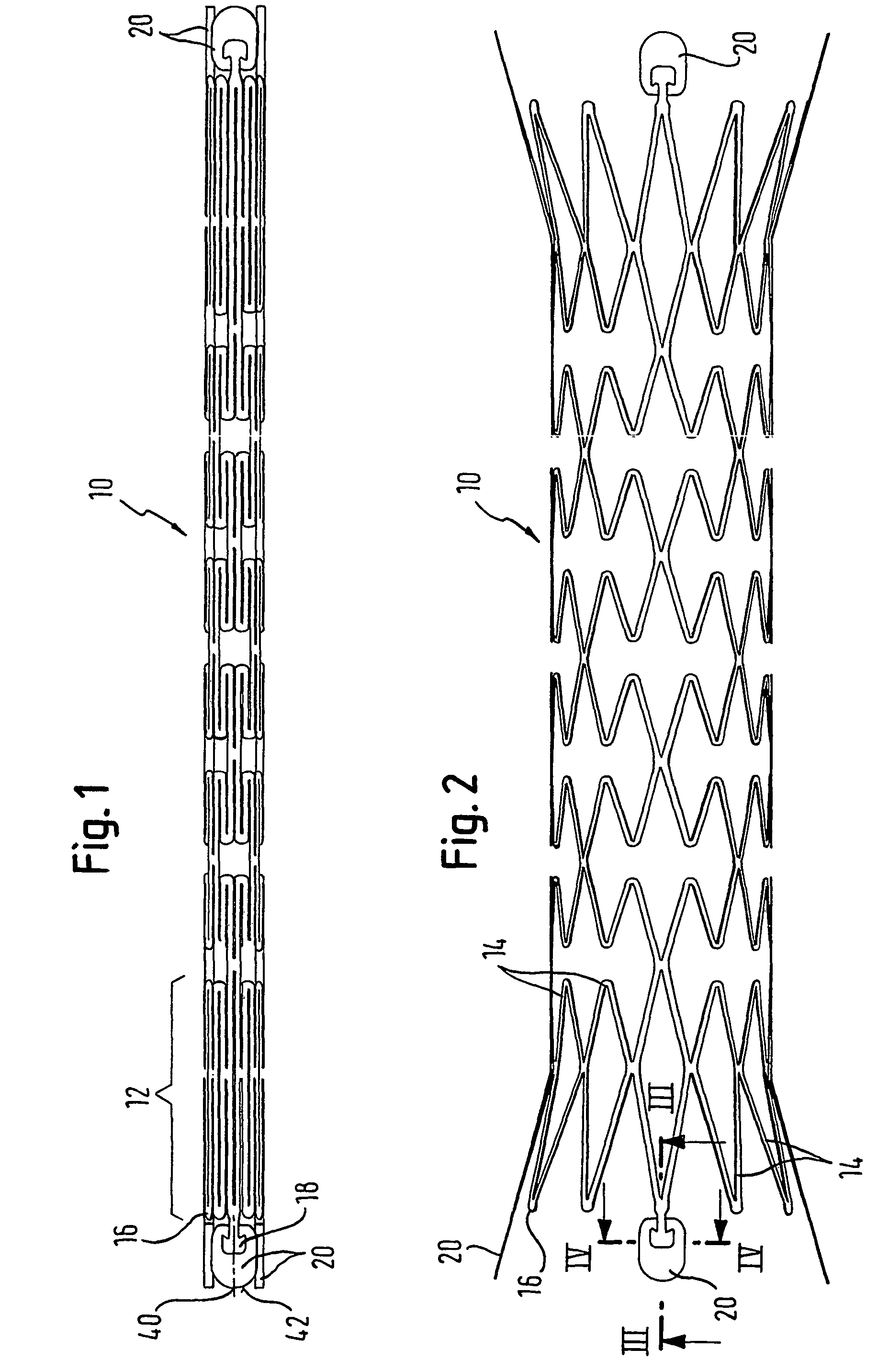
[0044]Skilled readers will appreciate that the material of the stent tube and its markers lies all in a circular cross-section with a wall thickness as small as possible, so as to be consistent with the objective of maintaining a bodily lumen as open as possible. The stent cylinder can be formed from seamless tubular starting material, or from flat material rolled into a tube (which thus exhibits some sort of seam).

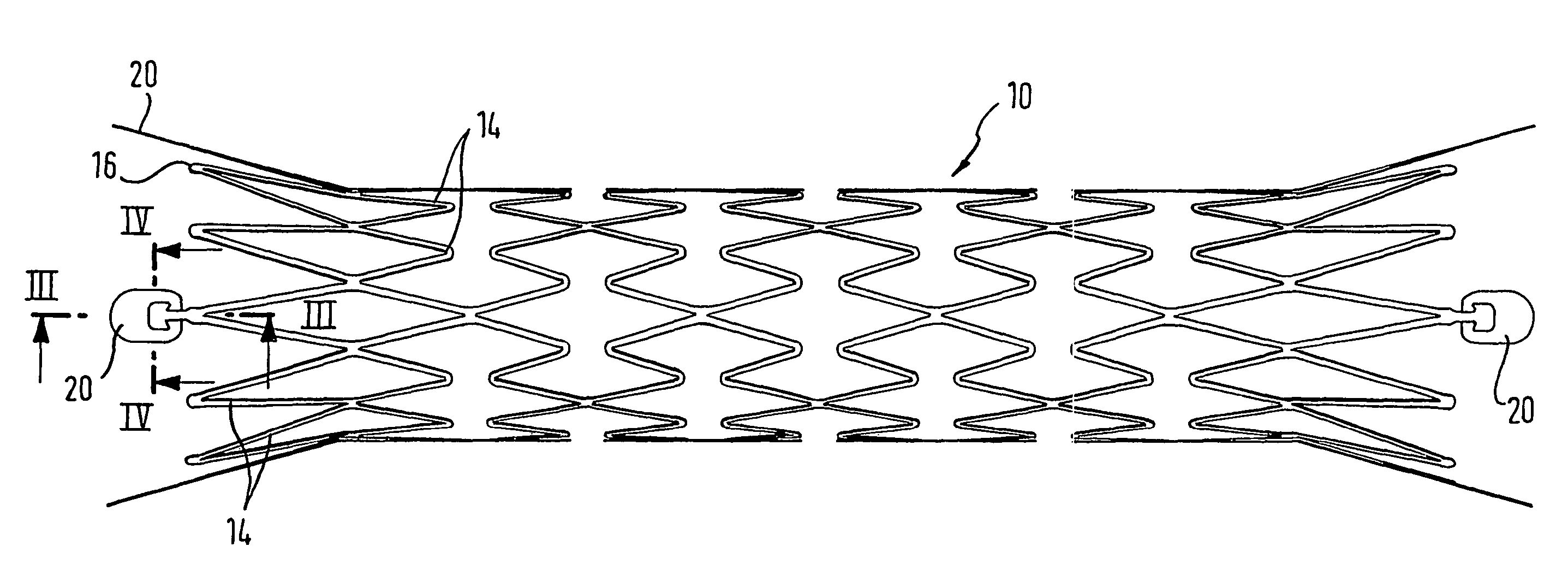
[0045]Skilled readers will also be well aware that there have been a very large number of proposals for strut patterns in the tubular configurations of stents. Whereas FIG. 1 shows an expandable strut pattern in a form which is particularly preferred for the present Applicant, nevertheless any other strut pattern will have points in it which define an end to the cylinder of the stent, and therefore will have points at the ends of the stent cylinder where markers can be attached.

[0046]Readers will also appreciate that self-expanding stents are delivered to stenting locatio...


PUM

PropertyMeasurementUnit
melting pointaaaaaaaaaa
diameteraaaaaaaaaa

Abstract

A tubular implant having an axial end to which is attached a ring of spoons of a material different from that of the implant. In another aspect, the invention provides a method of attaching elements to an axial end of a tubular implant comprising the steps of providing said elements on one end of a support tube having a radius substantially that of the implant in its unexpanded configuration, abutting the implant and elements end-to-end, fixing the elements to the implant; and parting the elements from the support tube. In a third aspect, the invention provides an implant carrying an element of another material, the element and implant having complementary tapered mating surfaces for achieving a taper form fit of the element onto the implant.

Description

FIELD OF THE INVENTION[0001]This invention relates to an implant, such as a stent formed from a stent material, to which is attached at least one element, such as a marker, made from a different material, such as a material having a radiopacity greater than that of the implant material. The invention also relates to a method of making such an implant.[0002]Although the present invention has particular usefulness for attaching radiopaque markers to stents, it also has application to implants (filters, for example) other than stents, and to elements other than markers. Such elements could function as, for example, drug delivery vehicles, trauma inhibitors, or connectors to link the implant to another implant or to an implant extraction tool.BACKGROUND ART[0003]WO-A-95 / 03010 discloses a stent in the form of a metal tube having a long axis, a luminal surface and an abluminal surface, and a tube wall thickness, the tube carrying within the wall thickness a radiopaque marker made of a met...

Claims


Application Information

Patent Timeline
Patent Type & Authority Patents(United States)
IPC IPC(8): A61F2/82A61L31/00A61F2/00A61F2/91A61F2/915A61F2/966A61L31/18
CPCA61F2/91A61L31/18A61F2/89A61F2/915A61F2230/0067A61F2002/91508A61F2002/91525A61F2002/91541A61F2002/91558A61F2002/9665A61F2250/0039A61F2250/0098A61F2220/005A61F2220/0058A61F2230/0054A61L31/022
Inventor LOMBARDI, SYLVIESUPPER, WOLFGANGBRIEST, ARNEGARNER, WALTER
Owner ANGIOMED GMBH & CO MEDIZINTECHNIK KG
Why Eureka
Try Eureka