
Device for simulating rectified constant impedance load and method thereof

a constant impedance load and device technology, applied in the direction of instruments, power supply testing, conversion with intermediate conversion to dc, etc., can solve the problems of inconvenient adjustment of resistor value, capacitance value or induction value, and how to figure out the disadvantages of prior art, so as to achieve convenient application

Active Publication Date: 2011-10-25
CHROMA ATE
View PDF3 Cites 8 Cited by
  • Summary
  • Abstract
  • Description
  • Claims
  • Application Information

AI Technical Summary

Benefits of technology

[0012]The primary objective of the present invention is to provide a device for simulating a rectified constant impedance load. The device is smaller in order to be convenient for application and precisely simulates the characteristics of a practical circuit consisted of several passive components so as to respond the output voltage of a tested object in time.

Problems solved by technology

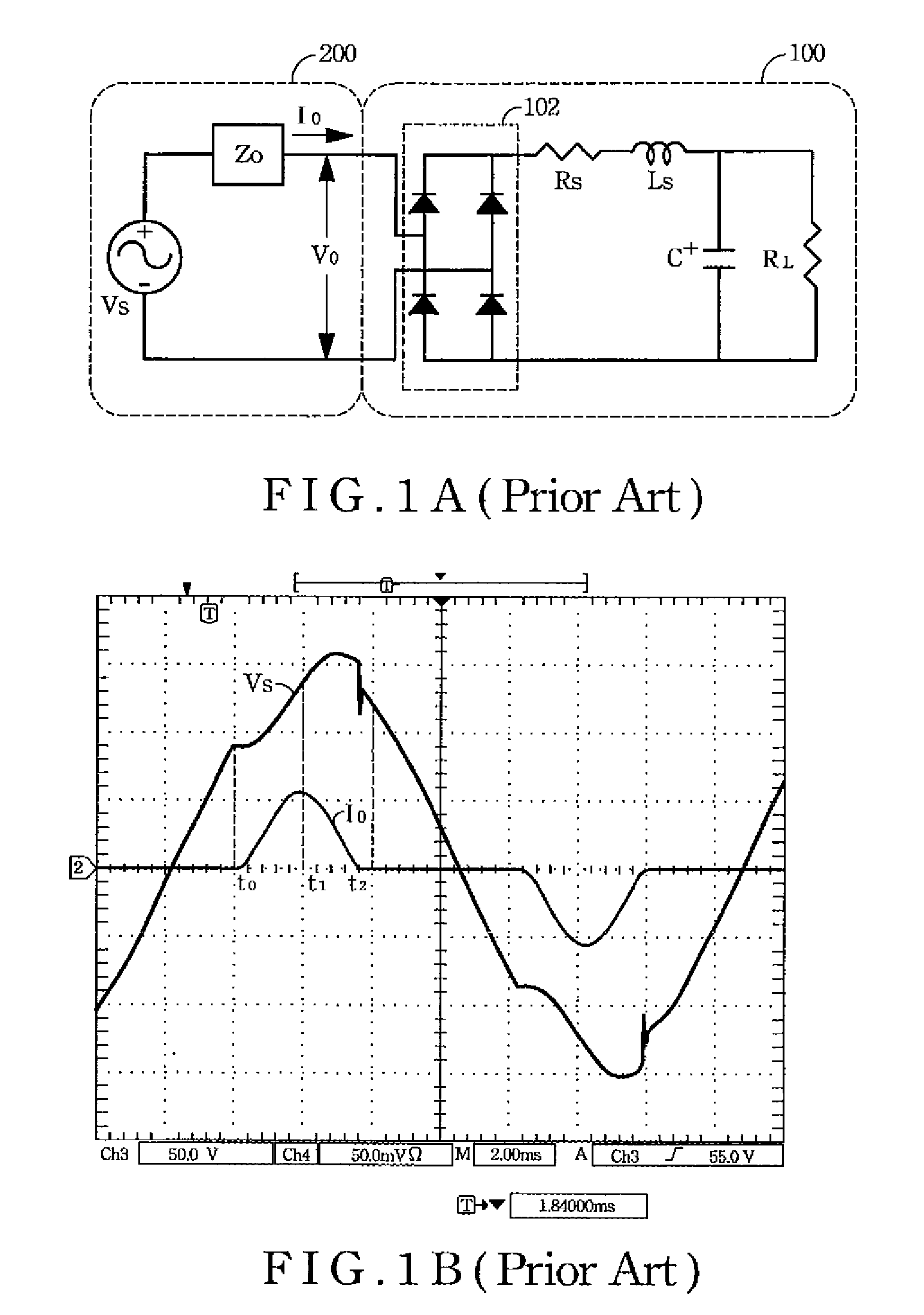
The disadvantage of such circuit is the volume thereof will be huge while demanding larger power; and it is inconvenient to adjust resistor value, capacitance value or induction value.
However, general AC electrical load only provides the functions with certain currents, certain power, etc.
Therefore, how to figure out the disadvantages of prior arts is an important issue to the skilled people in the art.

Method used


Image

  • Device for simulating rectified constant impedance load and method thereof
  • Device for simulating rectified constant impedance load and method thereof
  • Device for simulating rectified constant impedance load and method thereof

Examples


Embodiment Construction

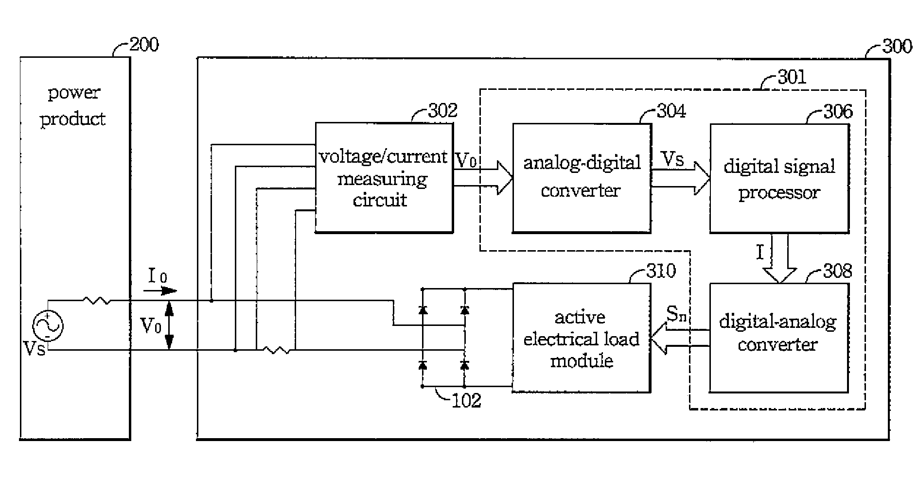
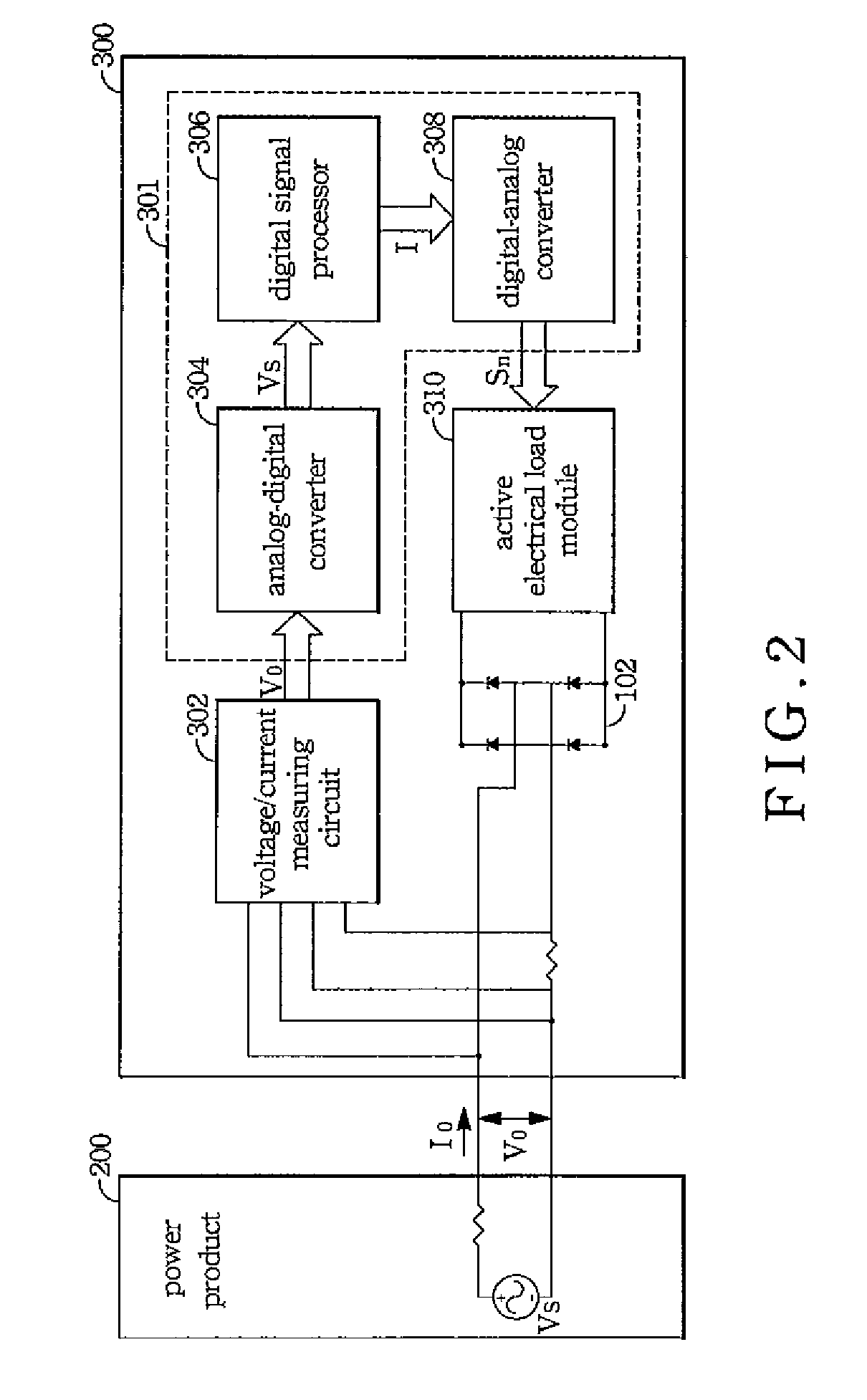
[0024]The present invention adopts the cooperation of digital control technology and an active electrical load module, a voltage / current measuring circuit, and a high-speed equipment, such as digital signal processor (DSP), analog-digital converter (ADC), digital-analog converter (DAC), etc. for simulating rectified constant impedance load circuits. A user is able to input the setting values of a serial resistance Rs, a serial inductance Ls, a load capacitance C, and a load resistance RL based on demands and refer to the voltage of a tested object in time. Continuously, a load current is calculated by the digital control technology and high-speed digital hardware, and then load drawing to the tested object is being processed. The load characteristics of RLCs can be simulated so as to decrease the volume of the load and increase the convenience to operations.

[0025]Following will be the figures of the present invention and the preferred embodiments, which describe in detail.

[0026]With...


PUM


Abstract

The device for simulating a rectified constant impedance load provide by the present invention is to test a power product and comprises an analog-digital converter, a digital signal processor, a digital-analog converter, and an active electrical load module in order to replacing the passive components of a traditional rectified passive load. method for simulating a rectified constant impedance load being applied to test a power product and comprising the steps of: (S1) replacing the plurality of passive components of the rectified constant impedance load with a digital control module and an active electrical load module; (S2) establishing a passive load model function in order to represent the application relationships of the plurality of the passive components; (S3) executing the operation of the passive load model function by the digital control module in order to gain a load current value, and transferring the load current value to an analog control signal via the digital control module; and (S4) controlling the active electrical load module via the analog control signal so as to draw currents from the power product.

Description

BACKGROUND OF THE INVENTION[0001]1. Field of the Invention[0002]The present invention generally relates to a device for simulating a rectified constant impedance load and a method thereof, more particularly to a device that simulates a rectified constant impedance load via an active electrical load.[0003]2. Description of the Prior Art[0004]An AC power product, such as UPS, etc., is widely applied in our normal life. And the scope of such application comprises general information, communication, consumer electronics, transportations, industry, military, etc. The functions to the power products are to drive electrical components and maintain voltages so as to keep a whole system working well. Hence, the main factors to the design of a power device are to decrease cost and increase liability.[0005]General AC power products are mostly for routine works, and sometimes are no-loaded. The load characteristic of the routine work equipment is RLC (resistor, inductor, capacitor) load. Theref...

Claims


Application Information

Patent Timeline
Patent Type & Authority Patents(United States)
IPC IPC(8): G01R31/40G06F15/00
CPCG01R31/2848G01R31/42
Inventor KAO, HUNG-HSIANGCHEN, WEN-CHUNGLIU, KUO-CHENGTSOU, MING-YING
Owner CHROMA ATE
Learn More