
Apparatus and method for signal detection in a cognitive radio-based wireless communication system

a wireless communication system and cognitive radio technology, applied in the field of cognitive radio (cr)based wireless communication systems, can solve the problems of limited spectrum available, many issues to be handled, and the deployment of a new wireless platform faces a serious shortage of spectrum resources, so as to prevent performance degradation

Active Publication Date: 2011-10-25
SAMSUNG ELECTRONICS CO LTD
View PDF15 Cites 4 Cited by
  • Summary
  • Abstract
  • Description
  • Claims
  • Application Information

AI Technical Summary

Benefits of technology

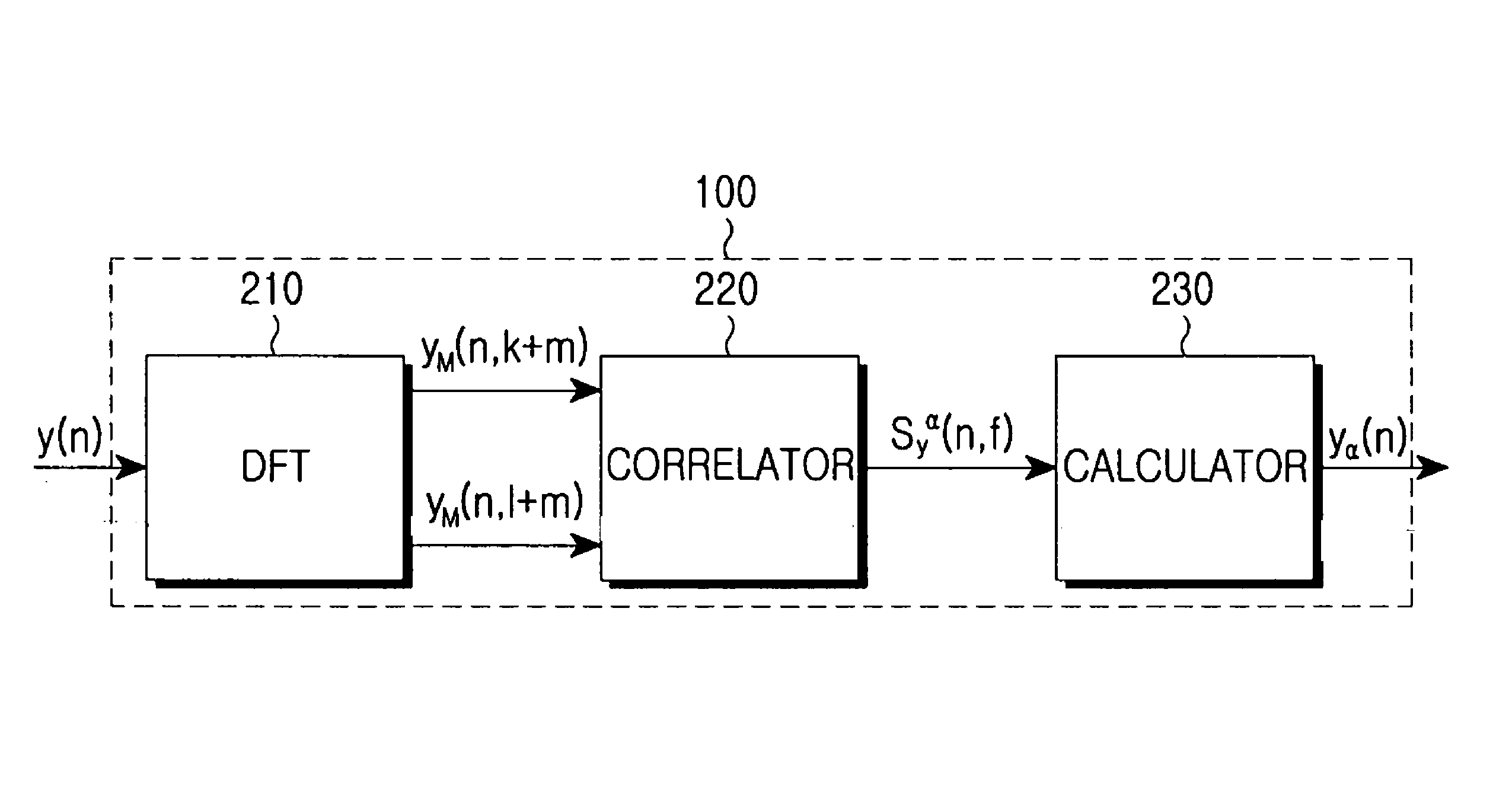
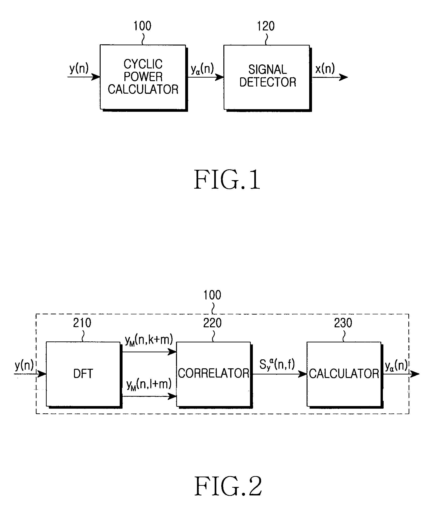
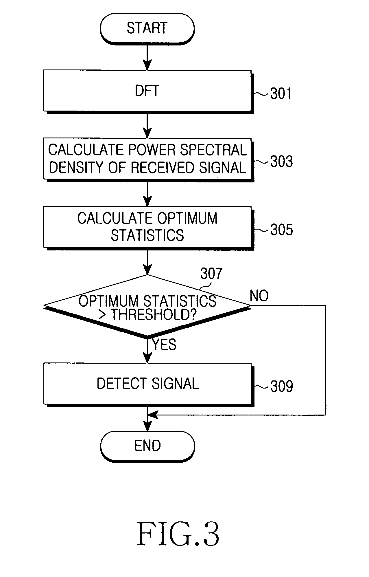
The present invention provides an apparatus and method for detecting a TV signal in a CR-based wireless communication system. The apparatus calculates the power spectral density of a cyclo-stationary and periodic signal, and optimizes the statistics using the power spectral density to determine whether a signal is detected or not. This approach ensures reliability and prevents performance degradation in the wireless communication system. The method also includes a discrete input signal processing and a DFT-based signal detection. Overall, the invention provides a more efficient and reliable solution for detecting TV signals in a CR-based wireless communication system.

Problems solved by technology

Yet, there is only a limited spectrum available due to multiple applications over all of frequencies which can be commercially used.
Hence, deployment of a new wireless platform faces a serious shortage of spectrum resources, particularly in lower frequency bands than a few gigahertz.
Hence, there exist many issues to be handled and most of the configurations for the CR technology are yet to be specified.
However, there are challenging issues to tackle in the application of CR to actual wireless communication systems.
However, the conventional signal detection method cannot ensure reliability and suffers performance degradation.

Method used


Image

  • Apparatus and method for signal detection in a cognitive radio-based wireless communication system
  • Apparatus and method for signal detection in a cognitive radio-based wireless communication system
  • Apparatus and method for signal detection in a cognitive radio-based wireless communication system

Examples


Embodiment Construction

[0025]Preferred embodiments of the present invention will be described herein below with reference to the accompanying drawings. In the following description, well-known functions or constructions are not described in detail since they would obscure the invention in unnecessary detail.

[0026]Before describing an apparatus and method for signal detection in a CR-based wireless communication system according to the present invention, a stationary process will be described.

[0027]The stationary process is a process in which the joint probability distribution of a random vector (X(t1), X(t2), . . . X(tn)) is equal to that of a random vector (X(t1+s), X(t2+s), . . . X(tn+s)), for all of N, s, t1, t2, . . . , tn.

[0028]The probability of distribution of a random vector is dependent only on a period n, but constant in time.

[0029]As an example, if stock price follows the stationary process, the probability distribution of tomorrow's stock price calculated today is equal to that of the next day...


PUM


Abstract

An apparatus and method for signal detection in a CR-based wireless communication system are provided. In the signal detection apparatus, a cyclic power calculator calculates the power spectral density of a cyclo-stationary and periodical signal to be detected with respect to a cyclic frequency and calculates optimum statistics using the power spectral density. A signal detector determines whether a signal exists or not according to the optimum statistics.

Description

PRIORITY[0001]This application claims priority under 35 U.S.C. §119 to applications entitled “Apparatus and Method for Signal Detection in a Cognitive Radio-based Wireless Communication System” filed in the U.S. Patent and Trademark Office on Nov. 3, 2005 and assigned Ser. No. 60 / 733,304, filed on Nov. 4, 2005 and assigned Ser. No. 60 / 733,858, and an application filed in the Korean Intellectual Property Office on Jun. 2, 2006 and assigned Ser. No. 50082-2006 the contents of each of which are incorporated herein by reference.BACKGROUND OF THE INVENTION[0002]1. Field of the Invention[0003]The present invention relates generally to a Cognitive Radio (CR)-based wireless communication system, and in particular, to an apparatus and method for detecting a Television (TV) signal on a radio channel.[0004]2. Description of the Related Art[0005]Along with the rapid development of wireless communication systems and a variety of wireless communication services, strict frequency separation is req...

Claims


Application Information

Patent Timeline
Patent Type & Authority Patents(United States)
IPC IPC(8): H03D1/00H04L27/06
CPCH04B17/327H04L27/0012
Inventor ASHISH, PANDHARIPANDE
Owner SAMSUNG ELECTRONICS CO LTD
Learn More