Curved surface forming method of a metal plate

a metal plate and forming method technology, applied in the field of curved surface forming method of metal plates, can solve the problems of inability to manufacture various curved surfaces, difficulty in maintaining uniform quality, and inability to use line heating methods in conjunction with computer systems, etc., to achieve constant quality, reduce the total time taken to manufacture the desired target, and reduce the curved surface forming time.

Inactive Publication Date: 2011-10-25
PAIK JEOM KEE
View PDF10 Cites 6 Cited by
  • Summary
  • Abstract
  • Description
  • Claims
  • Application Information

AI Technical Summary

Benefits of technology

[0018]As described above, according to the present invention, a three-dimensional curved plate having a target curved surface can be formed in an objective, uniform process without depending on the subjective experience of a skilled worker, so that the process of forming a desired target from the metal plate is very stable.
[0019]Further, whenever the metal plate is formed, the process is uniformly performed according to a scheduled procedure, so that a constant level of quality can be maintained. Particularly, compared to an existing manual forming method, which is based on experience, the curved surface forming time of the metal plate is remarkably reduced, so that the total time taken to manufacture the desired target can be reduced, which is very favorable from an economic standpoint.

Problems solved by technology

However, it is impossible in practice to manufacture them using a lightweight die made of a thick metal plate, etc. having various curved surfaces in the aspects of cost, time and so on.
However, since this line heating method is highly dependent on the proficiency and experience of a worker, recently it has been very difficult to maintain uniform quality due to the aging and attrition of skilled workers.
Furthermore, this line heating method is impossible to use in conjunction with a computer system, and thus has a limitation in the improvement of working efficiency.
In contrast, in the case in which small quantity batch production is required, meaning the case in which the number of curved plates to be worked is small, the stationary die module is manufactured at an enormous cost, and thus is impractical to apply in reality.
At present, these curved plates are mainly formed by the hot working method, and thus encounter the difficulties described above.
When the cold working method is applied, the number of workable workpieces is limited.
In the case in which small quantity batch production is required, it is impossible in practice to design and manufacture the stationary die module.
However, when a metal plate is plastic-worked by the hydraulic press, spring-back inevitably occurs.
In the complicated three-dimensional curved surface forming of the metal plate, spring-back is extremely complicated.
In order to obtain a target curved surface, a skilled worker must repeat the hydraulic pressing several times. As a result, there is a possibility of causing local damage to the worked workpiece.
In this manner, a sophisticated, complicated process must be conducted by a highly skilled worker.
Consequently, it takes a long time to manufacture the workpiece, and the quality of the formed workpiece varies according to the proficiency of the worker.
Thus, a limitation on the efficiency of production stems from the shortage of workers.

Method used


Image

  • Curved surface forming method of a metal plate
  • Curved surface forming method of a metal plate
  • Curved surface forming method of a metal plate

Examples


Embodiment Construction

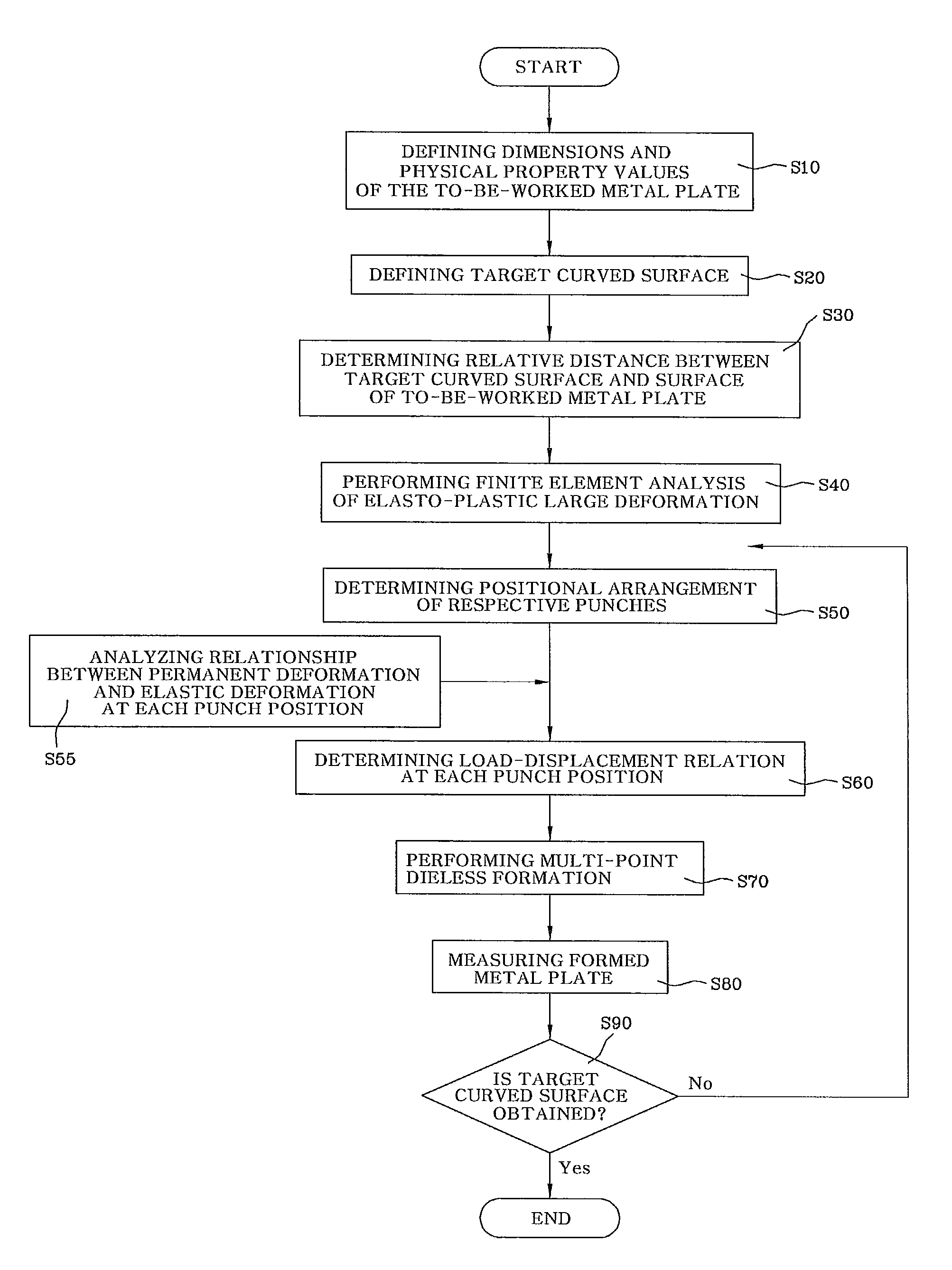
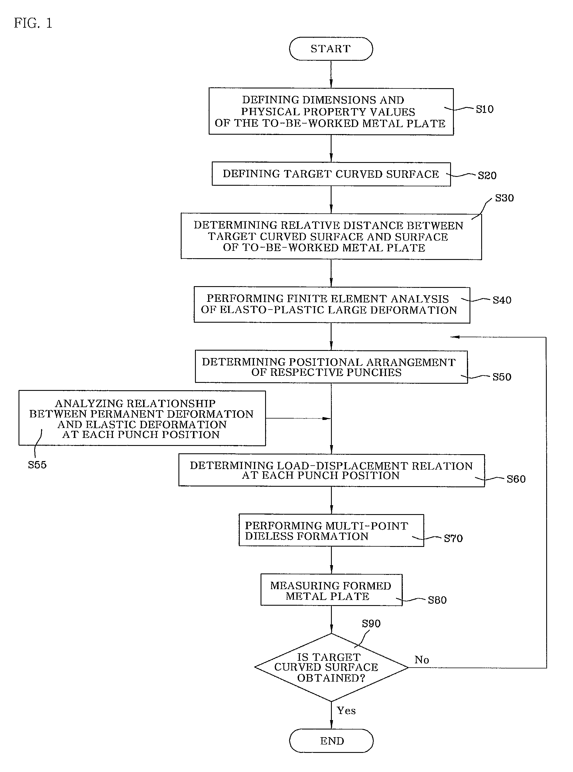
[0030]Hereinafter, the technical principle of the present invention will be described with reference to the accompanying drawings. FIG. 1 is a process flow chart illustrating a curved surface forming method for a metal plate according to the present invention. FIG. 2 is a system configuration view illustrating one example of a curved surface forming system for a metal plate according to the present invention.

[0031]As illustrated in FIG. 2, the curved surface forming system, that is, the multi-point dieless forming system, according to the present invention fundamentally comprises a computer system 110, a controller 120, a forming apparatus 130, and a measuring device 140. The computer system 110 serves to input basic information for analyzing and working a metal plate to be worked, performs finite element analysis, and transmits information on the analysis results to the controller 120 connected to the forming apparatus 130. Further, the computer system 110 may store information on ...


PUM

PropertyMeasurementUnit
shapeaaaaaaaaaa
physical propertyaaaaaaaaaa
relative distanceaaaaaaaaaa

Abstract

Disclosed is a curved surface forming method for a metal plate. Nonlinear finite element analysis of elasto-plastic large deformation is performed on the metal plate. The metal plate to be worked is formed so as to have a three-dimensional target curved surface on the basis of the analysis results using a plurality of forming punches connected to a hydraulic apparatus. The curved surface formation method is very useful when the metal plate is worked for small quantity batch production.

Description

TECHNICAL FIELD[0001]The present invention relates to a curved surface forming method for a metal plate and, more particularly, to a curved surface forming method for a metal plate, which calculates required load and displacement by nonlinear finite element analysis of elasto-plastic large deformation of a metal plate with the aid of a dedicated program or a commercial program as is convenient for a user, and forms a target curved surface using a multi-point dieless forming apparatus.BACKGROUND ART[0002]Typically, bodies of vehicles, etc. are manufactured by pressing a metal thin plate into a pre-designed die. However, it is impossible in practice to manufacture them using a lightweight die made of a thick metal plate, etc. having various curved surfaces in the aspects of cost, time and so on.[0003]General curved surface forming methods for a metal plate can be roughly classified into a cold forming method and a hot forming method. The hot forming method comprises bending a steel pl...

Claims


Application Information

Patent Timeline
Patent Type & Authority Patents(United States)
IPC IPC(8): G06F19/00B21C51/00B21D55/00B21D7/14
CPCB21D13/02B21D22/06B21D37/02
Inventor PAIK, JEOM KEE
Owner PAIK JEOM KEE
Why Eureka
Try Eureka