Heat treatment system

A heat treatment system and heat treatment device technology, applied in heat treatment furnaces, heat treatment equipment, furnace types, etc., can solve problems such as long mechanical downtime, reduced heat treatment efficiency, and pauses

Inactive Publication Date: 2006-10-25
NTN CORP
View PDF1 Cites 0 Cited by
  • Summary
  • Abstract
  • Description
  • Claims
  • Application Information

AI Technical Summary

Problems solved by technology

[0009] In addition, in the invention disclosed in the above text, a total of two kinds of heat treatment, i.e., main heat treatment and sub-heat treatment, are carried out, but since the heating time required for the main heat treatment is different from the heating time required for the sub-heat treatment, the heating time

Method used


Image

  • Heat treatment system
  • Heat treatment system
  • Heat treatment system

Examples


Embodiment Construction

[0042] The first embodiment of the present invention is described below, which is applied to a bearing component as an example of a steel component.

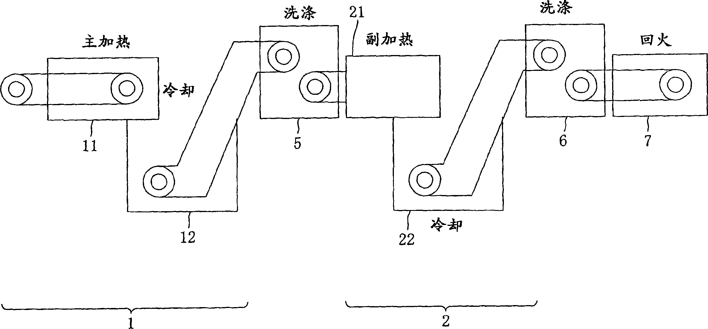
[0043] figure 1 It is a schematic diagram of the heat treatment system according to the present invention. As shown in the figure, this heat treatment system includes a main heat treatment device 1, a secondary heat treatment device 2, two washing devices 5 and 6, and a tempering device 7. The bearing parts produced by molding methods (not shown in the figure) such as forging and then turning are successively sent through the main heat treatment device 1 and the auxiliary heat treatment device 2, and are subjected to the main heat treatment and the auxiliary heat treatment in each of the above devices. Heating and cooling.

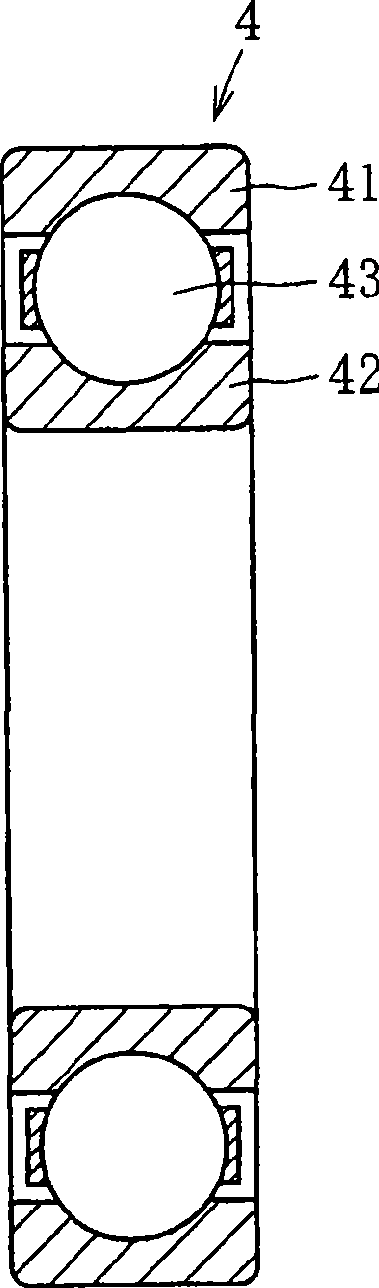
[0044] The term "bearing component" refers to the bearing component of a rolling bearing such as a ball bearing, tapered roller bearing, roller bearing or needle bearing. As an example, figure 2 Represents a ...


PUM


Abstract

In the formation of a nitrogen enriched layer in primary heat treatment and performing of re-quenching in secondary heat treatment, it is intended to enhance the efficiency of heat treatment with respect to the whole system. In primary heat treatment apparatus (1), bearing parts are heated by means of heater (11) to temperature exceeding the transformation point of Al and thereafter cooled by means of cooler (12) to temperature below the transformation point of Al so that a nitrogen enriched layer is formed on the surface thereof. The bearing parts after the primary heat treatment are subjected to high-frequency heating by means of heater (21) of secondary heat treatment apparatus (2) to temperature exceeding the transformation point of Al and thereafter cooled by means of cooler (22) to temperature below the transformation point of Al. After the cooling by means of cooler (22), tempering is performed by high-frequency heating.

Description

Technical field [0001] The invention relates to a heat treatment system for two-stage heat treatment of steel parts. Background technique [0002] Japanese Patent Publication No. 2003-226918 discloses an example of a heat treatment method, which is suitable for steel parts requiring rolling fatigue and long service life, such as bearing parts of rolling bearings. This method includes the following steps: subjecting the steel of the bearing component to carbonitriding treatment at a carbonitriding temperature exceeding the A1 transformation point, then cooling the steel to a temperature lower than the A1 transformation point, and then heating and The steel is quenched in the quenching temperature zone (790°C to 830°C) that exceeds the A1 transformation point but is lower than the carbonitriding temperature. [0003] According to this method, the carbonitriding layer existing on the steel surface increases the hardness of the bearing component. Because the quenching temperature in ...

Claims


Application Information

Patent Timeline
IPC IPC(8): C21D9/40C21D1/06C21D1/18C22C38/00
Inventor 中岛硕一前田喜久男
Owner NTN CORP
Why Eureka
Try Eureka