
Smart card with self-detachment features and related methods

a technology of self-detachment and smart cards, applied in the field of information processing and storage, can solve the problems of large system bus bandwidth and attempted unauthorized communication, and achieve the effects of reducing the likelihood of being compromised, reducing the likelihood of being damaged, and robust cpus

Active Publication Date: 2011-10-25
STMICROELECTRONICS SRL
View PDF19 Cites 4 Cited by
  • Summary
  • Abstract
  • Description
  • Claims
  • Application Information

AI Technical Summary

Benefits of technology

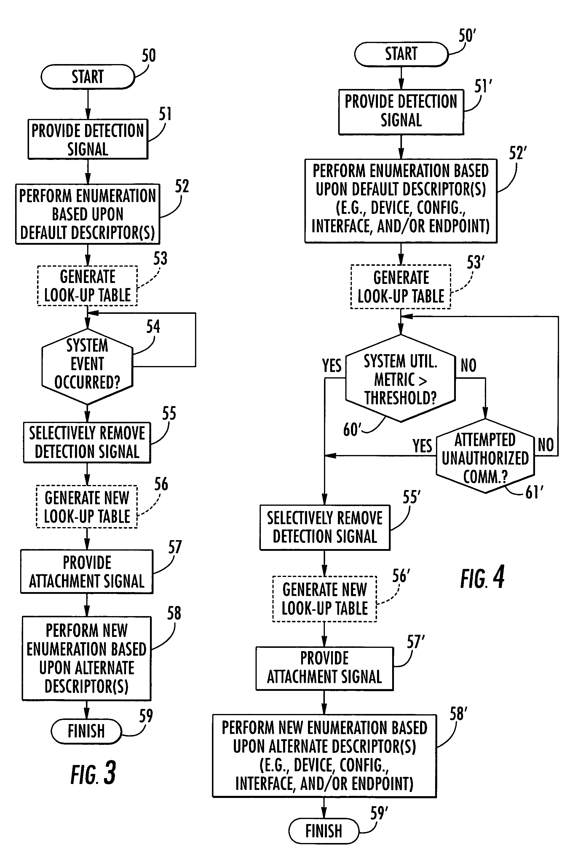
[0016]Another example of a system event may be the occurrence of attempted unauthorized communications. That is, if the processor perceives an attack on the system by an unauthorized user or eavesdropper, it may remove the attachment signal and then re-enumerate using a more secure configuration to reduce the likelihood of being compromised by such an attack.
[0017]It should be noted that traditional ISO smart cards will go “mute” under such circumstances. However, current smart card designs generally have fairly robust CPUs, more memory, improved anti-tamper mechanisms, etc., as well as some additional (and previously unseen) evasion possibilities. Also, USB allows VSR enumeration / re-enumeration, multiple communication pipelines, USB on-the-go, etc. As the world expands for today's smart cards, so to does their ability to act and react to perceived attacks, while still keeping their propriety architectures secure.

Problems solved by technology

More particularly, the processor may detect certain system events which may make the current or default settings established based upon the at least one default descriptor undesirable, and, in response, remove the attachment signal from the at least one data terminal and re-enumerate to change the default settings.
For example, several devices could be connected to the host device which consume large amounts of system bus bandwidth.
Another example of a system event may be the occurrence of attempted unauthorized communications.

Method used


Image

  • Smart card with self-detachment features and related methods
  • Smart card with self-detachment features and related methods
  • Smart card with self-detachment features and related methods

Examples


Embodiment Construction

[0025]The present invention will now be described more fully hereinafter with reference to the accompanying drawings, in which preferred embodiments of the invention are shown. This invention may, however, be embodied in many different forms and should not be construed as limited to the embodiments set forth herein. Rather, these embodiments are provided so that this disclosure will be thorough and complete, and will fully convey the scope of the invention to those skilled in the art. Like numbers refer to like elements throughout, and prime notation is used to indicate similar elements in alternate embodiments.

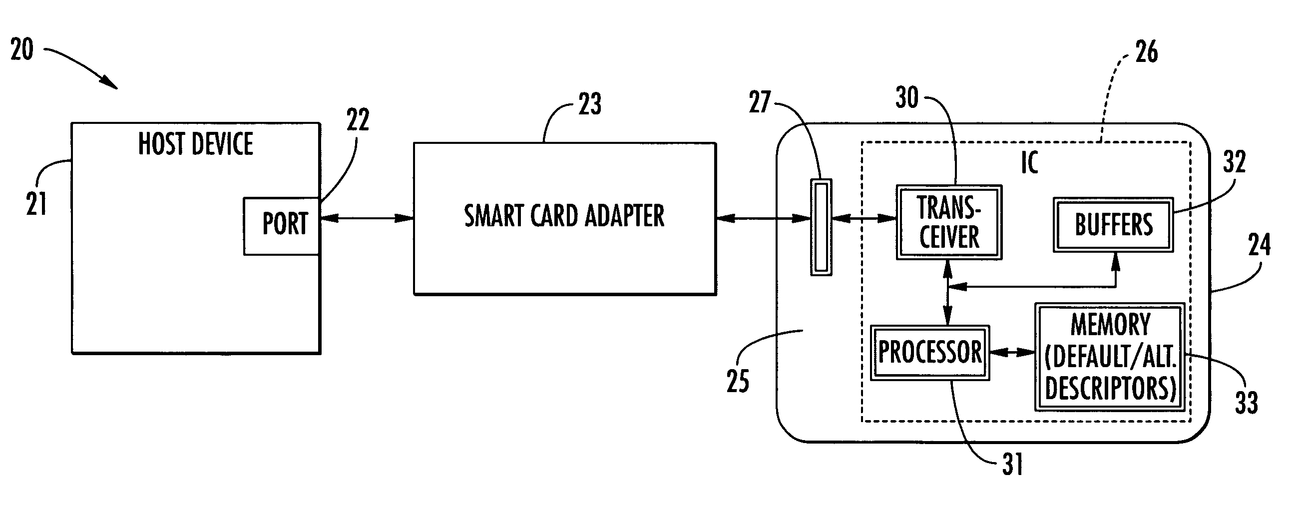
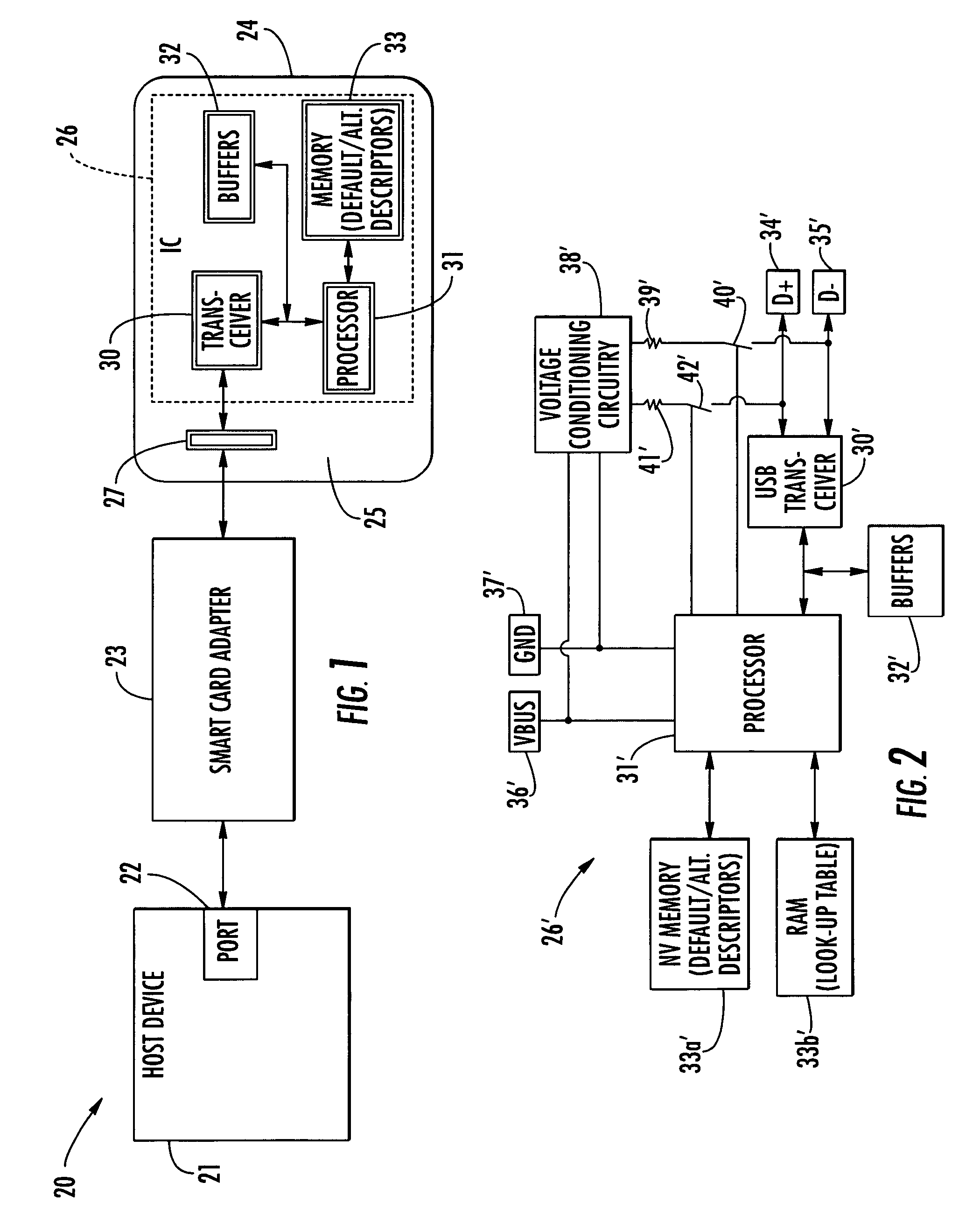
[0026]Referring initially to FIG. 1, a smart card system 20 in accordance with the present invention illustratively includes a host device 21 having a communications port 22, a smart card adapter or adapter 23 connected to the communications port, and a smart card 24 to be read by the smart card adapter. Generally speaking, the host device 21 will be a computer of some type, ...


PUM


Abstract

An integrated circuit for a smart card in accordance with an exemplary embodiment includes at least one data terminal for providing communications with a host device and a processor for providing an attachment signal on the at least one data terminal for recognition by the host device. Further, the processor also cooperates with the host device to perform an enumeration based upon at least one default descriptor. In addition, based upon a system event, the processor selectively removes the attachment signal from the at least one data terminal and thereafter again provides the attachment signal on the at least one data terminal and cooperates with the host device to perform a new enumeration based upon at least one alternate descriptor.

Description

FIELD OF THE INVENTION[0001]The present invention relates to the field of information processing and storage, and, more particularly, to smart cards and related methods.BACKGROUND OF THE INVENTION[0002]Smart cards are becoming increasingly more popular for security and personal identification applications. For example, smart cards are currently used for storing sensitive data such as medical records, banking information, etc. In perhaps their most common form, smart cards have a card body which resembles a credit card in size, shape, and thickness, and they may even be made out of similar materials, such as plastic. Yet, rather than simply having a magnetic stripe to store sensitive information (e.g., account numbers, user identification, etc.) as standard credit cards do, smart cards generally include an integrated circuit (IC). The IC not only includes a non-volatile memory for storing such sensitive information, but it may also include a microprocessor for processing this informa...

Claims


Application Information

Patent Timeline
Patent Type & Authority Patents(United States)
IPC IPC(8): G06F13/00G06F3/00
CPCG06K19/07
Inventor LEAMING, TAYLOR J.
Owner STMICROELECTRONICS SRL
Learn More