Method and apparatus for sample injection in liquid chromatography

a liquid chromatography and sample technology, applied in bends, instruments, transportation and packaging, etc., can solve the problems of liquid pressure in the fluid circuit upstream of the obstruction, significant flow and pressure transients in the mobile phase stream, and temporary blockage of the flow path between the pump and the column

Active Publication Date: 2011-11-01
WATERS TECH CORP
View PDF20 Cites 23 Cited by
  • Summary
  • Abstract
  • Description
  • Claims
  • Application Information

AI Technical Summary

Benefits of technology

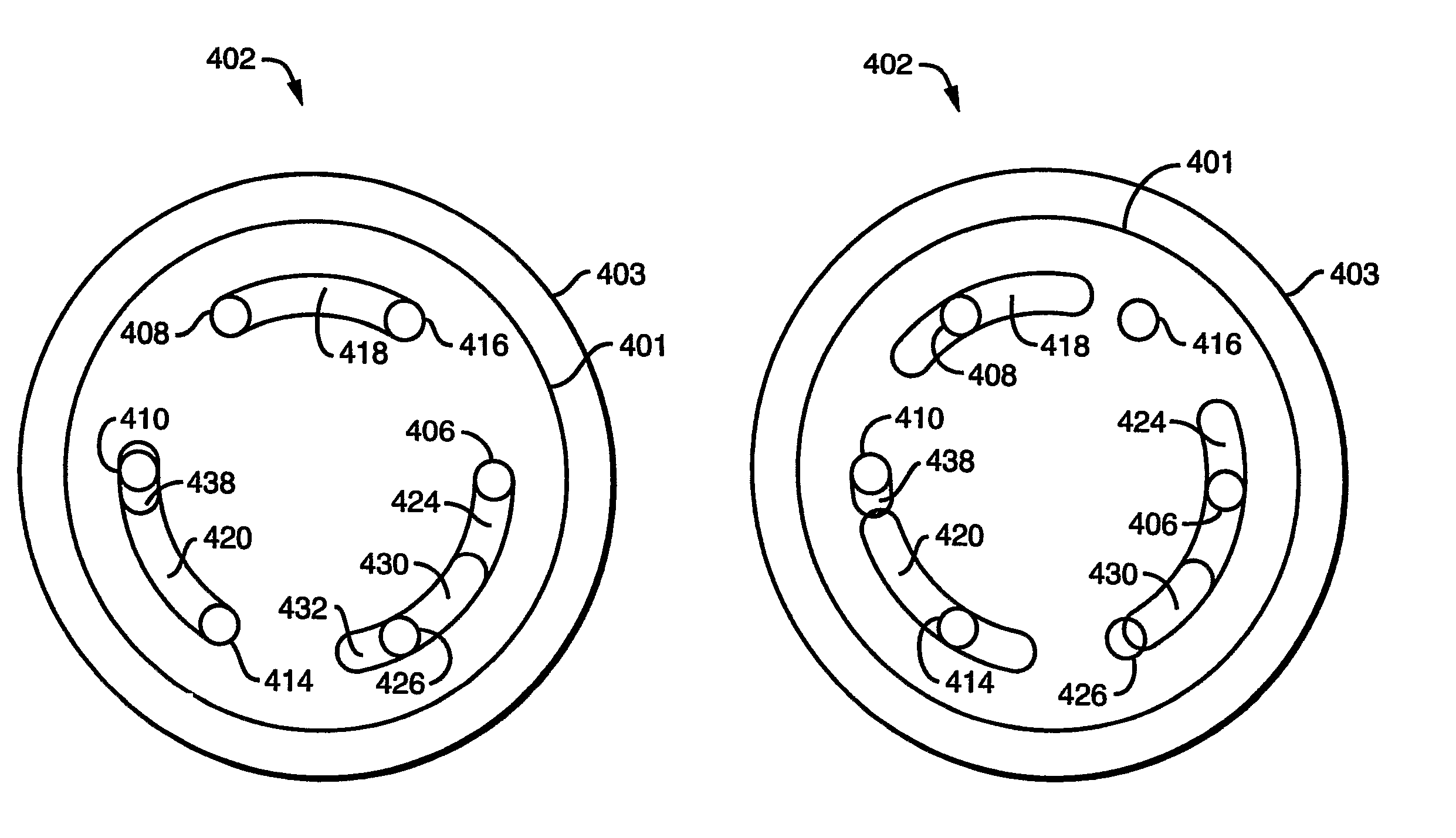
[0032]Another advantage of the present invention is the adaptability of the configurations of the rotor channels and stator ports and port channels. Various arrangements of extended channels in the rotor and expanded or extended ports in the stator can similarly substantially eliminate destructive transients of flow rate and pressure.
[0033]Yet a further advantage of the present invention is the ability to control the direction of compression of the sample loop contents during the sequence of events leading to sample injection into the high pressure mobile phase stream, in addition to controlling the direction of decompression of the sample loop contents when the loop is removed from the high pressure mobile phase stream and its contents are decompressed prior to the aspiration of a subsequent sample.

Problems solved by technology

An undesirable attribute shared by conventional rotary shear seal injection valves is that during transition between the LOAD and INJECT state, or between the INJECT and LOAD state, the flow path between pump and column is temporarily blocked.
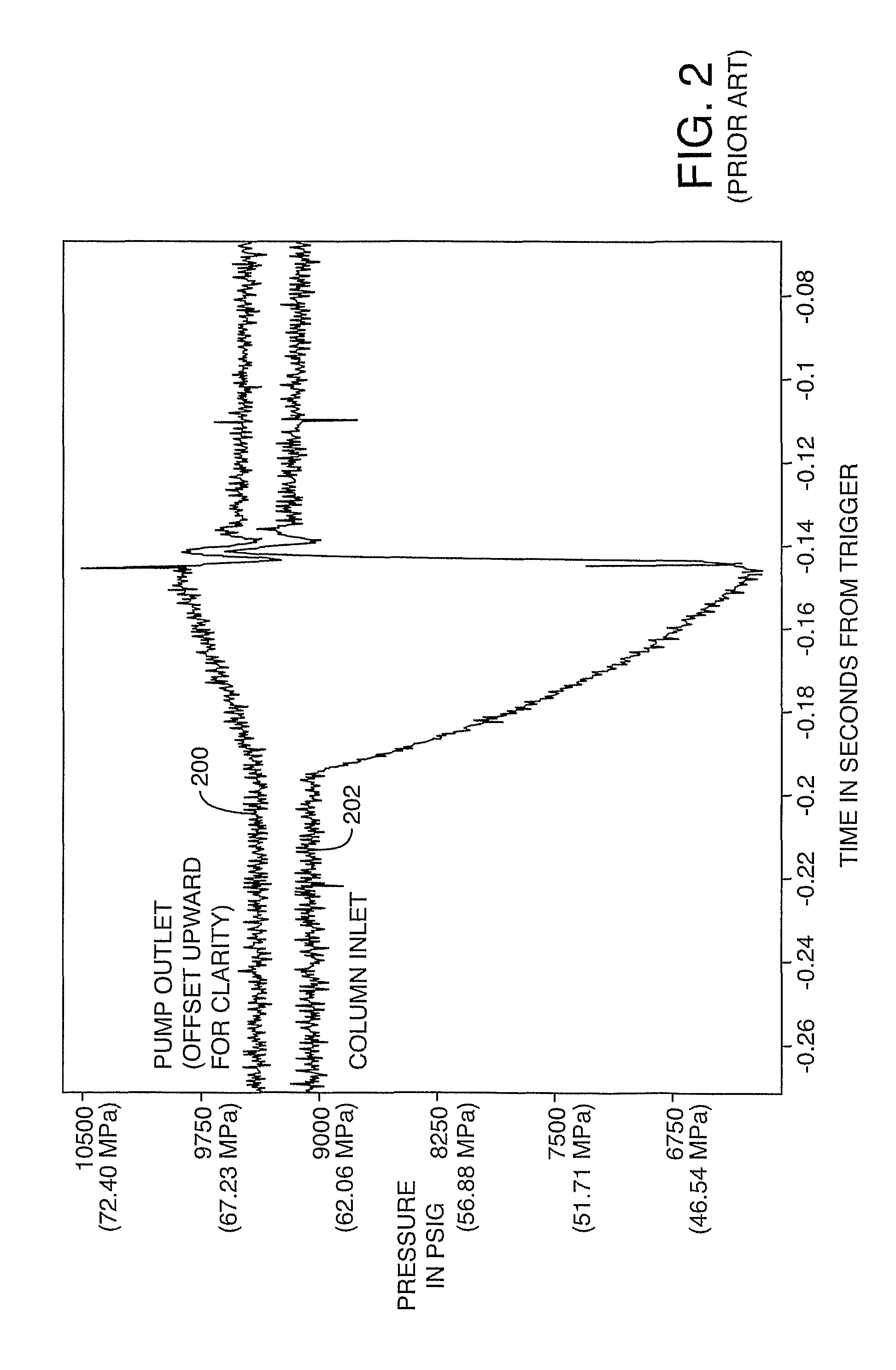
Even at conventional HPLC flow rates and pressures, break-before-make switching of the fluid path internal to the sample injection valve gives rise to very significant flow and pressure transients in the mobile phase stream.
During the time interval in which the pump-to-column flow is obstructed, the pump continues to source mobile phase into a now dead-ended fluid path, causing the liquid pressure in the fluid circuit upstream of the obstruction to rise.
Because of the relative stiffness of liquids, a flow blockage of approximately one hundred to several hundred milliseconds duration can lead to a significant pressure differential being imposed across the injection valve.
These transients typically become more severe as system operating pressure increases, or as the pre-column system volume decreases (the latter tending to reduce the parasitic fluid capacitance available to cushion the effect).
Abrupt transients of liquid flow rate and liquid pressure in the vicinity of the column head can be extremely disruptive to HPLC columns.
The disruptive effects upon the column are most readily observed as a loss of achievable separation efficiency for a defined separation which is performed repeatedly, or as a change (typically an increase) in the resistance to flow exhibited by the column, for a defined operating condition corresponding to a prescribed mobile phase composition, flow rate, and column temperature.
Unfortunately, in VHPLC system operation, even a 50 millisecond flow blockage can lead to dramatic column impairment.
In that context, a 50 millisecond break-before-make switching behavior is highly significant, and a valve exhibiting that duration of complete flow blockage is substantially inadequate to address the column degradation problem.
Poor matching of the purging rates of these two parallel paths can lead to corruption of the gradient profile.
In addition to the above considerations, the resistive bypass injector as implemented by Abrahams and Hutchins is generally more complex and more expensive to manufacture than a conventional multi-port rotary shear seal valve.
While the resistive bypass injector configuration substantially circumvents the problem of flow blockage transients, it shares with the shear seal injection valve the undesirable characteristic of causing a loop charging transient when the un-pressurized sample is exposed to system pressure.
In a VHPLC system, the loop charging transient may be the dominant transient associated with sample injection, and under worst-case conditions of a large sample loop with air-gaps present, may result in a nearly instantaneous and substantially complete depressurization of the column head, with attendant destructive impact upon the column.

Method used


Image

  • Method and apparatus for sample injection in liquid chromatography
  • Method and apparatus for sample injection in liquid chromatography
  • Method and apparatus for sample injection in liquid chromatography

Examples


Embodiment Construction

[0056]Detailed embodiments of the present invention are disclosed herein, however, it is to be understood that the disclosed embodiments are merely exemplary of the invention, which may be embodied in various forms. Therefore, specific functional details disclosed herein are not to be interpreted as limiting, but merely as a basis for the claims and as a representative basis for teaching one skilled in the art to variously employ the present invention in virtually any appropriately detailed embodiment.

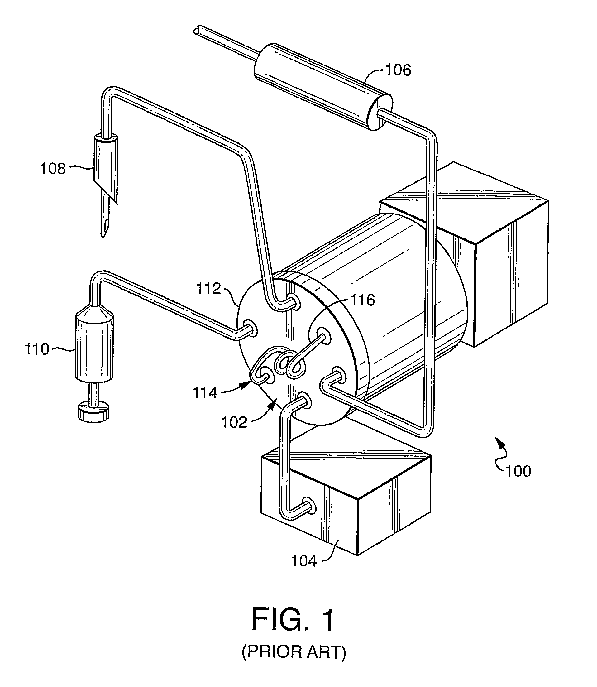
[0057]Turning to FIG. 1, a simplified block diagram of a standard arrangement of an HPLC system 100 utilizing a rotary shear-seal injection valve 102 is shown. Rotary shear seal injection valve 102 is connected to a mobile phase pump 104. The pump 104 delivers mobile phase liquid through selected internal fluid pathways of rotary shear seal injection valve 102. A separation column 106 is also connected to the rotary shear seal injection valve. Separation column 106 acts in concert with...


PUM

PropertyMeasurementUnit
mean diameteraaaaaaaaaa
time durationaaaaaaaaaa
timeaaaaaaaaaa

Abstract

The present invention provides a method and apparatus for substantially eliminating destructive transients of pressure or flow rate which can degrade the efficiency and useful lifetime of chromatography columns. The present invention enables a substantially constant flow of mobile phase liquid to be maintained through the chromatography system by eliminating the flow blockage interval associated with the actuation of sample injection valves. The present invention further provides a method to reduce the pressure and flow rate transients associated with pressurization of the sample loop contents when the sample loop is introduced to chromatography system delivery pressure.

Description

CROSS REFERENCE TO RELATED APPLICATIONS[0001]This application is the National Stage of International Application No. PCT / US2006 / 003248, filed on Jan. 31, 2006, which claims priority from U.S. Provisional Patent Application No. 60 / 648,540 filed on Jan. 31, 2005. The entire contents of these applications are incorporated herein by reference.FIELD OF THE INVENTION[0002]The present invention relates to high pressure liquid chromatography, particularly to a sample injection subsystem used to introduce sample for analysis by the high pressure liquid chromatography system.BACKGROUND OF THE INVENTION[0003]The introduction of sample into a high pressure liquid chromatography (“HPLC”) analysis system is normally accomplished through the operation of an apparatus termed a sample injector, which is interposed in the HPLC system fluid circuit downstream of the mobile phase delivery pump(s) and upstream of the analytical column. This configuration accomplishes a substantially direct introduction ...

Claims


Application Information

Patent Timeline
Patent Type & Authority Patents(United States)
IPC IPC(8): G01N1/00G01N30/00
CPCG01N30/20G01N30/22G01N2030/202Y10T137/0396Y10T137/4636Y10T137/86863
Inventor DOURDEVILLE, THEODORE A.KEENE, RUSSELL L.CIOLKOSZ, THEODORE D.USOWICZ, JAMES E.
Owner WATERS TECH CORP
Why Eureka
Try Eureka